Ó
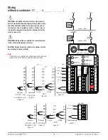
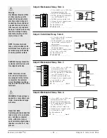
Warning:
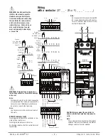
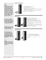
Use National Electric (NEC)
or other country-specific
standard wiring and safety
practices when wiring and
connecting this controller to
a power source and to elec-
trical sensors or peripheral
devices . Failure to do so may
result in damage to equip-
ment and property, and/or
injury or loss of life .
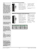
NOTE: To prevent ground
loops, isolation needs to be
maintained from input to out-
put when using switched DC
or analog process outputs .
CAUTION: Always mount the
controller with the heat-sink
fins aligned vertically .
NOTE: Terminals L4 and
A1 on the limit connector
are jumpered at the factory
to complete the contactor
circuit . Additional switches
may be wired in series to the
terminals .
Ó
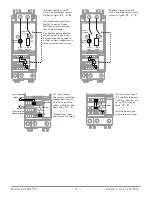
WARNING: If high voltage is
applied to a low-voltage con-
troller, irreversible damage
will occur .
Watlow EZ-ZONE
®
ST
•
20
•
Chapter 2 Install and Wire
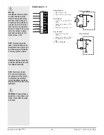
Digital Input 5 - 6
B5
D6
D5
DC Input
common
DC Input
Slot C
Digital Input
• Update rate 1 Hz
• Dry contact or dc voltage
DC Voltage
• Input not to exceed 36V at
3 mA
• Input active when > 3V @
0.25 mA
• Input inactive when < 2V
Dry Contact
• Input inactive when >
500 Ω
• Input active when < 100 Ω
• maximum short circuit 13
mA
ST
[B, C, D or E]
_- _ _ _ _-_
_ _ _
Voltage Input
B
common
Vdc
D
_
_
Dry Contact
B
common
24 Vdc
_
_
D

