Watlow EZ-ZONE
®
ST
•
26
•
Chapter 2 Install and Wire
Setting the Address
Modbus Controller Address
The address of an EZ-ZONE
®
ST controller with the
Modbus option (ST _ _-_ _ M _-_ _ _ _) can be set to
ranges from 1 to 8 using the DIP switch and ranges
1 to 247 using software.
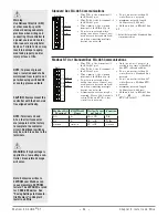
Set switch 4 to on to use Modbus communications.
Modbus™ RTU addresses from 1 to 247 can be pro-
grammed into the controller using Standard bus
communications. Only one controller can be con-
nected to the network while changing the address
using communications. After the Modbus address is
changed, all four DIP switches must be turned on
(set to 8) and the controller restarted for the new ad-
dress be become available on the Modbus network.
The Modbus addresses set by software will override
only address 8, but lower addresses set on the DIP
switch will override the software-assigned addresses.
As many as 247 controllers can be connected to a
network.
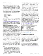
The Standard bus address of an EZ-ZONE ST con-
troller with the Modbus™ RTU option (ST _ _-_ _ M
_-_ _ _ _) ranges from 1 to 8, because DIP switch 4 is
reserved for switching Modbus on or off.
DIP Switch
Zone
1
2
3
**4
1
off
off
off
on
2
on
off
off
on
3
off
on
off
on
4
on
on
off
on
5
off
off
on
on
6
on
off
on
on
7
off
on
on
on
**8
on
on
on
on
**1 to 247
on
on
on
on
** Set switch 4 to on to use Modbus communications . Mod-
bus addresses from 1 to 247 can be programmed into the
controller using Standard bus communications when switch
4 is off . After the Modbus address is changed, all four DIP
switches must be turned on (set to 8) for the new address to
become available on the Modbus network .
1 2 3 4
ON
98
99
CF
CD
CE
B5
D6
D5
L2
K2
T1
S1
R1
L3
K3
J3
A1
L4
T2
S2
R2
2
1
EZ-ZONE™ ST
Patent Pending
Integrated Control Loop
LIMIT
OUT 3
SSR
STATUS
OUT 2
Control
Address
Selection
Communica-
tions
Parameter
Name
Range
Modbus
(less 400,001
offset)
Data
Type
&
Read/
Write
Address (when
all four DIP
switches are set
to on)
* 1
to 247
Map 1 Map 2
313
2052
uint
RW
Baud
* 9,600
(188)
19,200 (189)
38,400 (190)
Map 1 Map 2
314
2054
uint
RWE
Parity
Even (191)
Odd (192)
* None
(61)
Map 1 Map 2
315
2056
uint
RWE
Word Order
* Lowhigh
(1331)
Highlow (1330)
Map 1 Map 2
- - - - 2058
uint
RWE
Non-Volatile
Save
(ST Firmware 2
and higher)
* Yes
(106)
No (59)
Map 1 Map 2
317
2084
uint
RWE
* Defaults
Note:
Changing the Modbus parameters listed above
must be done over Modbus using ST firmware re-
lease 2.0 and earlier. For firmware release 3.0 and
above using either an RUI or EZ-ZONE Configura-
tor software, navigate to the Setup Page and then
to the Com
[Com]
(RUI representation) menu to
change.
CAUTION:
Changes set over Modbus are immediate. Users will
not be able to communicate with the controller after
its address, parity or baud rate has been changed.
The master device will need to be re-configured to
the new settings.
Saving Settings to Nonvolatile Memory
When controller settings are entered using the op-
tional RUI, changes are always saved to Non-volatile
Memory (EEPROM). If the controller loses power or
is switched off, its settings will be restored when it
starts again.
The EEPROM will wear out after about 1,000,000
writes, which would not be a problem with changes
made from the RUI. However, if the controller is re-
ceiving changing instructions from a PLC or a com-
puter through a network connection, the EEPROM
could, over time, wear out. The Non-volatile Memory
Save parameter allows the user to save settings
made over the network to either volatile or non-
volatile memory.
By default, settings made through the network
are saved to non-volatile memory.
Note:
Changing Non-volatile Memory Save must be done
over the network using ST firmware release 2.0
and earlier. For firmware release 3.0 and above us-
ing either an RUI or EZ-ZONE Configurator soft-
ware, navigate to the Setup Page and then to the
Com
[Com]
(RUI representation) menu to change.

