Watlow EZ-ZONE
®
ST
•
39
•
Chapter 4 Setup Page
Chapter 4: Setup Pages
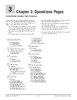
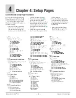
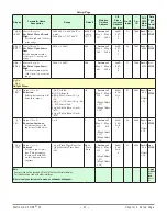
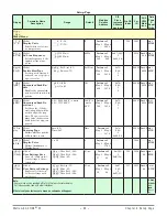
Control Module Setup Page Parameters
4
[``Ai]
[`Set]
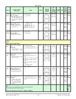
Analog Input Menu
[```1]
[``Ai]
Analog Input 1 (to 2)
[`SEn]
Sensor Type
[`Lin]
Linearization
[`rt;L]
RTD Leads
[Unit]
Units
[`S;Lo]
Scale Low
[`S;hi]
Scale High
[`r;Lo]
Range Low
[`r;hi]
Range High
[`P;EE]
Process Error Enable
[`P;EL]
Process Error Low
[`FiL]
Filter
[`i;er]
Error Latching
[`dEC]
Display Precision
[`s;ba]
Sensor Backup
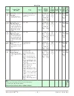
[`dio]
[`Set]
Digital Input/Output Menu
[```1]
[`dio]
Digital Input/Output 5 (to 6)
[`dir]
Direction
[``Fn]
Output Function
[``Fi]
Function Instance
[`o;Ct]
Control
[`o;tb]
Time Base
[`LEu]
Active Level
[``Fn]
Action Function
[``Fi]
Function Instance
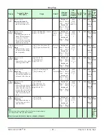
[LiM]
[`Set]
Limit Menu
[```1]
[LiM]
Limit 1
[`L;SD]
Sides
[`L;hy]
Hysteresis
[SP;Lh]
Set Point Limit High
[SP;LL]
Set Point Limit Low
[`L;it]
Limit Integrate
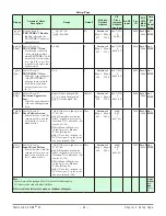
[Loop]
[`Set]
Control Loop Menu
[```1]
[Loop]
Control Loop 1
[`h;Ag]
Heat Algorithm
[`C;Ag]
Cool Algorithm
[t;tUn]
Tru-Tune+
®
Enable
[t;bnd]
Tru-Tune+ Band
[`t;gn]
Gain
[t;Agr]
Autotune Aggressiveness
[`P;dl]
Peltier Delay
[`UFA]
User Failure Action
[FAiL]
Input Error Failure
[MAn]
Manual Power
[`L;dE]
Open Loop Detect Enable
[`L;dt]
Open Loop Detect Time
[`L;dd]
Open Loop Detect Deviation
[``rp]
Ramp Action
[`r;SC]
Ramp Scale
[`r;rt]
Ramp Rate
[`L;SP]
Set Point Closed Limit Low
[`h;SP]
Set Point Closed Limit High
[SP;Lo]
Set Point Open Limit Low
[SP;hi]
Set Point Open Limit High
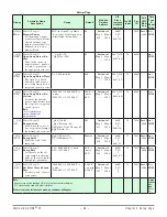
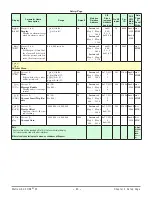
[otpt]
[`Set]
Output Menu
[```1]
[otpt]
Output 1 (to 4)
[``Fn]
Output (2 to 4) Function
[``Fi]
Function Instance
[`o;Ct]
Control
[`o;tb]
Time Base
[`o;Lo]
Low Power Scale
[`o;hi]
High Power Scale
[``Fn]
Output (1) Function
[ss;ti]
Soft Start Time
[ALM]
[`Set]
Alarm Menu
[```1]
[ALM]
Alarm 1 (to 2)
[`A;ty]
Type
[`sr;a]
Source
[`is;a]
Instance
[`A;hy]
Hysteresis
[`a;Lg]
Logic
[`A;SD]
Sides
[`a;LA]
Latching
[`A;bL]
Blocking
[`a;Si]
Silencing
[A;dsp]
Display
[`A;dL]
Delay
[CUrr]
[`Set]
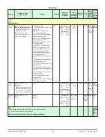
Current Menu
[```1]
[CUrr]
Current 1 (to 4)
[`C;Sd]
Sides
[`C;Ur]
Read Enable
[`C;le]
Limit Enable
[`C;dt]
Detection Threshold
[C;ofs]
Heater Current Offset
[`fUn]
[`Set]
Function Key Menu
[```1]
to
[```2]
[`fUn]
Function Key
[``Fn]
Event Function
[``fi]
Function Instance
[gLbL]
[`Set]
Global Menu
[```1]
[gLbl]
Global
[`C_F]
Display Units
[AC;LF]
AC Line Frequency
[p;typ]
Profile Start Type
[`gse]
Guaranteed Soak Enable
[gsd1]
Guaranteed Soak Deviation
[d;prs]
Display Pairs
[USr;S]
User Settings Save
[USr;r]
User Settings Restore
[COM]
[`Set]
Communications Menu
[```1]
[COM]
Communications
[ad;m]
Modbus Address
[bAUd]
Baud Rate
[`PAr]
Parity
[M;hL]
Modbus Word Order
[`C_F]
Display Units
[map]
Data Map
[`nu;s]
Non-Volatile Save
To go to the Setup Page from the
Home Page, press both the Up
¿
and Down
¯
keys for six seconds.
[``Ai]
will appear in the upper
display and
[`Set]
will appear in
the lower display.
• Press the Up
¿
or Down
¯
key to view available menus.
On the following pages top
level menus are identified with
a yellow background color.
• Press the Advance Key
‰
to
enter the menu of choice.
• If a submenu exists (more than
one instance), press the Up
¿
or Down
¯
key to select and
then press the Advance Key
‰
to enter.
• Press the Up
¿
or Down
¯
key to move through available
menu prompts.
• Press the Infinity Key
ˆ
to
move backwards through the
levels: parameter to submenu;
submenu to menu; menu to
Home Page.
•
Press and hold the Infinity
Key
ˆ
for two seconds to re-
turn to the Home Page.


