Watlow F4T Install & Troubleshooting
•
11
•
Chapter 2 Install and Wire
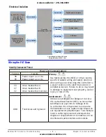
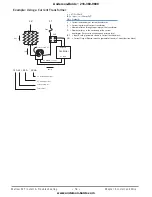
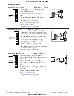
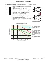
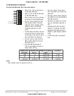
Place the Quencharc directly across the external coil as shown below. For a DC load, place
the cathode of the diode, to the positive voltage of the load and the anode to the ground of
the load.
Note:
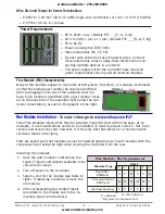
It is possible that the terminal strip labeling for any given module could be the same. For
example, if a Thermocouple input module is installed in slot 1 and 2, each slot would have
S1 and R1 on its label. When referencing either of these inputs the differentiating factor is
the module slot number, therefore the reference should be input 1 of slot number x.
Note:
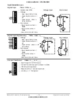
Maintain electrical isolation between the analog input, digital input-outputs, switched dc/
open collector outputs and process outputs to prevent ground loops.
Note:
The F4T meets IP10 requirements when the empty slots have slot caps installed.
Note:
Maximum wire size and torque for screw terminations:
• 0.0507 to 3.30 mm2 (30 to 12 AWG) single-wire termination or two 1.31 mm2 (16 AWG)
• 0.57 Nm (5.0 lb.-in.) torque
Input Connections
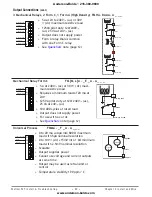
Thermocouple
FM [M, L] A - [L, U, Y] _ _ A - A _ _ _
S1
R1
•
Grounded or ungrounded sensors, greater than 20MΩ input imped
-
ance, 2kΩ source resistance max.
• 3 microampere open-sensor detection
• Thermocouples are polarity sensitive. The negative lead (usually red)
must be connected to S terminal
• To reduce errors, the extension wire for thermocouples must be of the
same alloy as the thermocouple.
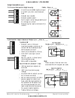
Thermocouple (High Density) FMHA - RAAA - A _ _ _
-
+
-
+
-
+
-
+
S1
R1
S2
R2
S3
R3
S4
R4
•
Grounded or ungrounded sensors, greater than 20MΩ input imped
-
ance, 2kΩ source resistance max
• 3 microampere open-sensor detection
• Thermocouples are polarity sensitive. The negative lead (usually
red) must be connected to S terminal
• To reduce errors, the extension wire for thermocouples must be of
the same alloy as the thermocouple
Quencharc
Watlow Part #: 0804-0147-0000
User Load
L_
K_
N
Anderson-Bolds ~ 216-360-9800
www.anderson-bolds.com


