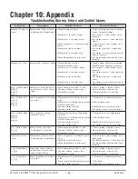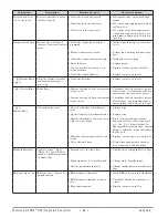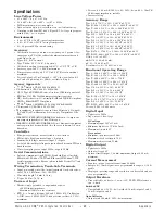
Wa t l o w E Z - Z O N E
®
P M I n t e g r a t e d C o n t r o l l e r
•
6 0
•
C h a p t e r 9 F e a t u r e s
Time
Te
mperature
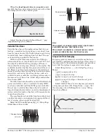
40%
Sensor
Break
2 minutes
Locks in
Output
Power
0%
Set Point
Actual Temperature
Output Power
Power
100%
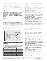
Input Error Latching
[`i;Er]
(Setup Page, Ana-
log Input Menu) determines the controller’s response
once a valid input signal returns to the controller.
If latching is on, then the controller will continue to
indicate an input error until the error is cleared. To
clear a latched alarm, press the Advance Key
‰
then
the Up Key
¿
.
If latching is off, the controller will automatically
clear the input error and return to reading the tem-
perature. If the controller was in the auto mode when
the input error occurred, it will resume closed-loop
control. If the controller was in manual mode when
the error occurred, the controller will remain in
open-loop control.
The Manual Control Indicator Light % is on when
the controller is operating in manual mode.
You can easily switch between modes if the Con-
trol Mode
[`C;M]
parameter is selected to appear in
the Home Page.
To transfer to manual mode from auto mode,
press the Advance Key
‰
until
[`C;M]
appears in
the lower display. The upper display will display
[AUto]
for auto mode. Use the Up
¿
or Down
¯
keys
to select
[Man]
. The manual set point value will be
recalled from the last manual operation.
To transfer to auto mode from manual mode,
press the Advance Key
‰
until
[`C;M]
appears in
the lower display. The upper display will display
[MAn]
for manual mode. Use the Up
¿
or Down
¯
keys to select
[AUto]
. The automatic set point value
will be recalled from the last automatic operation.
Changes take effect after three seconds or imme-
diately upon pressing either the Advance Key
‰
or
the Infinity Key
ˆ
.
On-Off Control
On-off control switches the output either full on or
full off, depending on the input, set point and hys-
teresis values. The hysteresis value indicates the
amount the process value must deviate from the set
point to turn on the output. Increasing the value de-
creases the number of times the output will cycle.
Decreasing hysteresis improves controllability. With
hysteresis set to 0, the process value would stay clos-
er to the set point, but the output would switch on
and off more frequently, and may result in the output
“ chattering.”
On-off control can be selected with Heat Algo-
rithm
[`h;Ag]
or Cool Algorithm
[`C;Ag]
(Setup Page,
Loop Menu).
On-off hysteresis can be set with Heat Hysteresis
[`h;hY]
or Cool Hysteresis
[`C;hY]
(Operations Page,
Loop Menu).
Note: Input Error Failure Mode
[faIl]
does not function in on-
off control mode. The output goes off.
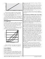
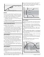
Set Point
Time
Temperature
The heating action switches off when the process
temperature rises above the set point.
The heating action
switches on at startup.
Hysteresis
Process Temperature
Hysteresis
Time
Temperature
The cooling action
switches
on at startup.
Process Temperature
The cooling action switches on when
the process temperature rises above
the set point plus the hysteresis.
Set Point
The heating action switches on when the process temperature
drops below the set point minus the hysteresis.
The cooling action switches off when the process
temperature drops below the set point.
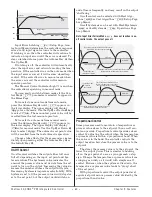
Proportional Control
Some processes need to maintain a temperature or
process value closer to the set point than on-off con-
trol can provide. Proportional control provides closer
control by adjusting the output when the temperature
or process value is within a proportional band. When
the value is in the band, the controller adjusts the
output based on how close the process value is to the
set point.
The closer the process value is to the set point, the
lower the output power. This is similar to backing
off on the gas pedal of a car as you approach a stop
sign. It keeps the temperature or process value from
swinging as widely as it would with simple on-off
control. However, when the system settles down, the
temperature or process value tends to “droop” short
of the set point.
With proportional control the output power level
equals (set point minus process value) divided by the
proportional band value.
Summary of Contents for Integrated Controller Rev C EZ-ZONE PM
Page 79: ......


