background image

3

For more cool and exciting Wattage products, visit our website at http://watt-age.globalhobby.com

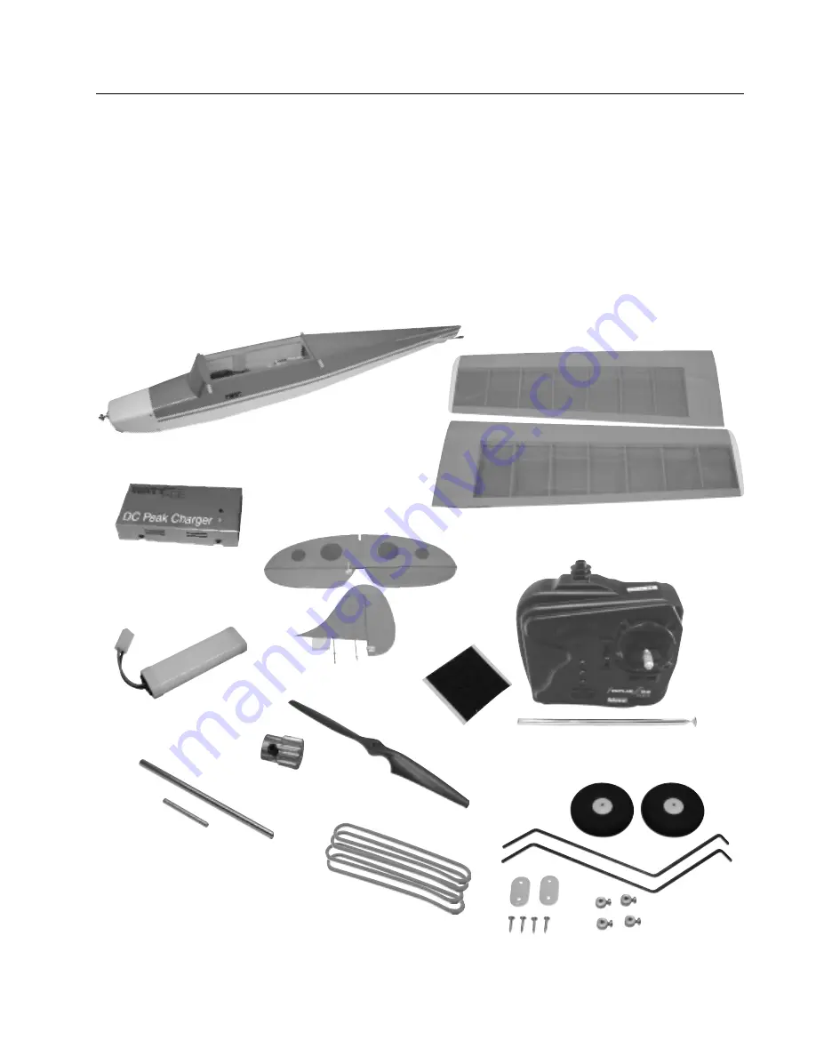
Fuselage Assembly

Wing Assembly

Tail Assembly

DC Peak Charger

Flight Battery

3ch. Transmitter

Propeller

Before beginning assembly, remove the different parts from the box and use the photos below to verify that your kit
contains all of the correct parts.  If your kit is missing a part, or if any parts appear to be damaged, please contact us
using the information below:

Wattage Customer Service

18480 Bandilier Circle

Fountain Valley  CA  92728

Phone (714) 963-0329

Fax (714) 964-6236

Email: service@globalhobby.net

Section 1:  Parts Identification

Landing Gear Assembly

Wing Joiners

Rubber Bands

Pinion Gear

Velcro

®

Not Pictured:

Adhesive Wing Tape (1)
Decal Sheet (1)
Transmitter Flag (1)

Summary of Contents for Ezette RTF

Page 1: ...ildren under 12 years of age should always be accompanied by an adult when either assembling or flying the airplane SAFETY WARNING This R C airplane is not a toy If misused it can cause serious bodily injury and or damage to property Fly only in open areas and preferably at a dedicated R C flying site We suggest having a qualified instructor carefully inspect your airplane before its first flight ...

Page 2: ...able flight characteristics With the Ezette electric powered flight has never been easier or more fun Features All wood construction Factory covered in real polyester covering Molded cowling is factory installed Includes a factory installed electric motor gear box and propeller Factory installed Hitec Focus III AM radio system with Wattage IC 380 Super ESC Includes two different motor pinion gears...

Page 3: ...os below to verify that your kit contains all of the correct parts If your kit is missing a part or if any parts appear to be damaged please contact us using the information below Wattage Customer Service 18480 Bandilier Circle Fountain Valley CA 92728 Phone 714 963 0329 Fax 714 964 6236 Email service globalhobby net Section 1 Parts Identification Landing Gear Assembly Wing Joiners Rubber Bands Pi...

Page 4: ... of problems that might occur If you cannot solve a problem using the troubleshooter or if you have any other questions or concerns please contact us using the information below Wattage Customer Service 18480 Bandilier Circle Fountain Valley CA 92728 Phone 714 963 0329 Fax 714 964 6236 E mail service globalhobby net FOR YOUR CONVENIENCE We have included a glossary of terms on page 29 Check it out ...

Page 5: ...e top of the transmitter Slide the end of the antenna down into the antenna mount Thread the antenna into the antenna mount and tighten it very lightly Do not overtighten the antenna or you could damage the transmitter Step 2 Installing the Transmitter Batteries Remove the battery cover from the bottom of the transmitter by pushing out with your thumb at the mark shown Section 3 Assembling Your Ez...

Page 6: ...he transmitter Install 8 fresh AA Alkaline batteries being careful to watch that the polarity is correct for each battery Slide the battery tray back into the transmitter making sure that the electrical contacts on the end of the tray match the contacts in the transmitter Push the battery cover back into place until you hear it click into position ...

Page 7: ...gs can be plugged in only one way When the charger is connected to its power source the red LED will blink on and off After you plug the flight battery into the charger the red LED will stop blinking and turn on solid This lets you know the charger is charging the battery Allow the charger to charge the battery The battery is fully charged when the green LED turns on IMPORTANT We strongly suggest ...

Page 8: ...globalhobby net Push the remaining shorter wing joiner into the rear hole using the same technique Step 4 Assembling the Wing Panels Carefully line up the longer of the two metal wing joiners with the forward hole in the end of one wing panel Push the wing joiner into the hole until it stops ...

Page 9: ...ing panels firmly together as shown The wing panels should fit tightly together Using scissors cut the length of adhesive wing joiner tape in half Remove the tape s protective backing and apply one strip of tape to the bottom of the wing joint and the other strip to the top of the wing joint Use scissors to trim the ends of the tape flush with the wing The tape will keep the wing panels from pulli...

Page 10: ...ertical tail with the two holes in the fuselage Step 5 Installing the Tail Assembly Remove the two hex nuts and two flat washers that are preinstalled on the tail mounting screws Carefully slide the horizontal tail into the slot in the fuselage Center the tail and push it forward completely Make sure the control horn is facing the bottom of the fuselage ...

Page 11: ...have to pivot the control surfaces so that the control horn will pass below the horizontal tail Slide one flat washer onto each mounting screw Thread one hex nut onto each mounting screw and tighten them finger tight Use an adjustable wrench to tighten the hex nuts firmly to draw the tail assembly down into place The tail assembly should be firmly tightened down against the fuselage Step 6 Install...

Page 12: ... straps into place using the four wood screws provided Tighten the screws firmly using a small phillips head screwdriver Firmly push both landing gear wires down into the holes and into the mounting slot Place both landing gear straps over the landing gear wires lining up the holes in the straps with the pilot holes in the fuselage ...

Page 13: ...a small phillips head screwdriver Slide one wheel onto the axle and push it up against the wheel collar Slide a second wheel collar assembly onto the axle Push the wheel collar up against the wheel and tighten the set screw The wheel should be able to spin freely If it doesn t readjust the wheel collar Repeat the previous steps to install the wheel and wheel collars on the other axle ...

Page 14: ...globalhobby net Push the propeller firmly onto the propeller mount Step 7 Installing the Propeller Remove the machine screw and flat washer from the propeller adapter Before installing the propeller make sure you orientate it properly The flat side of the propeller hub should face the adapter ...

Page 15: ... a 7 64 hex wrench Spin the propeller by hand If any part of it touches the cowling see page 27 to readjust the alignment of the motor Step 8 Applying the Decals Using a pair of scissors cut out each of the decals along their outer edges Remove the protective backing from the decals and carefully apply the decals to the airframe Use the box cover photos as a reference for the decal locations ...

Page 16: ... be toward the top of the fuselage Step 9 Installing the Flight Battery Pull the two pieces of Velcro apart Remove the protective backing from one piece of Velcro Apply that piece of Velcro to the battery as shown Make sure to apply the Velcro to the end of the battery where the wires come out Remove the protective backing from the remaining piece of Velcro Apply the piece of Velcro to the top por...

Page 17: ... from sliding around or backing out during flight Plug the connector on the flight battery into the connector that is inside the fuselage When plugged in properly you should hear the connectors click Note that the plugs can be plugged in only one way Step 10 Installing the Wing Set the wing onto the fuselage Line up the centerline of the wing with the centerline of the fuselage ...

Page 18: ...smitter check to make sure the switch on the side of the fuselage is off This will prevent unexpected radio signals from interfering with your radio system Install the rubber bands to hold the wing firmly in place Use two rubber bands per side four total to hold the wing in place It is not necessary to use more than four rubber bands but if you use less the wing may move during flight resulting in...

Page 19: ...n the airborne system ESC receiver and servos You should hear the servos center themselves Double check that the throttle lever is set to off This will prevent the propeller from spinning when you turn on the airborne system WARNING Keep clear of the propeller when turning on the airborne system and when working the controls IMPORTANT To prevent unwanted signals from interfering with the radio sys...

Page 20: ...e back of the Ezette RTF move the transmitter control stick completely to the left The vertical control surface should move left While holding the horizontal control surface even with the horizontal tail thread the clevis forward or back until it lines up with the holes in the control horn Snap the clevis into the outer hole While holding the vertical control surface even with the vertical tail th...

Page 21: ...r control stick completely to the right The vertical control surface should move right Looking from the back of the Ezette RTF move the transmitter controlstickcompletelyback Thehorizontalcontrolsurfaceshould move up Looking from the back of the Ezette RTF move the transmitter control stick completely forward The horizontal control surface should move down ...

Page 22: ...mend taking off or landing from hard surfaces like asphalt or concrete Step 2 Testing the Motor WARNING During the motor test keep everything clear of the propeller especially fingers and loose clothing While holding the Ezette RTF upright in the air with the propeller pointing away from you slide the throttle control lever completely to the right The propeller should spin at a high rate of speed ...

Page 23: ... fly There s too much wind Wait for a calmer day to fly Step 3 Range Testing the Radio System Plug in and install the flight battery Turn on the transmitter double check that the throttle lever is in the off position then turn on the airborne system Set the Ezette RTF on the ground With the transmitter s antenna fully collapsed move the control stick back and forth to check the controls Walk appro...

Page 24: ...ate battery packs can be purchased and charged before going to the flying field An extra flight battery will double your flight time See the replacement parts list on page 31 for the part number of the flight battery Do not fly in high winds otherwise the Ezette RTF will be difficult to control and a crash will likely occur Do not fly your Ezette RTF if another airplane is on the same frequency as...

Page 25: ... to hold a slight amount of back stick to keep the airplane level and prevent it from descending WARNING Do not try to climb until after the airplane picks up sufficient airspeed Climbing too steeply too quickly will result in a stall and crash Step 2 Flying After you ve launched the Ezette RTF and the flying speed has picked up keep the motor running at full power and apply a small amount of back...

Page 26: ...l itself from a shallow turn after releasing the control stick If you get into too sharp a turn or if you want to level the wings sooner apply a small amount of stick in the opposite direction that you turned When the wing levels off release the control stick Remember don t over control WARNING The longer you hold the control stick over the tighter radius the Ezette RTF will turn in We recommend g...

Page 27: ...ld be centered within the cowling opening and the propeller should not touch the cowling when it is turned Your Ezette RTF comes with a 14 tooth pinion gear 1 7 1 gear ratio preinstalled A second 12 tooth pinion gear 2 1 gear ratio is provided as an option The 14 tooth pinion gear provides excellent overall performance with extra speed Using the 12 tooth pinion gear will decrease the overall speed...

Page 28: ...age 20 C The flight battery is depleted C Land and recharge the flight battery D Transmitter batteries are depleted D Replace batteries with new ones E You are over controlling E Be careful not to over control Apply only small gentle control inputs 5 The Ezette RTF always A The left right trim lever is out of adjustment A Adjust the trim lever on the transmitter turns to the left or right until th...

Page 29: ... motor The Ezette s motor controller is pro portional with the throttle lever so you can reduce or increase speed smoothly Pushrods They connect the control surfaces to the servos transferring the movement of the servos directly to the control surfaces Receiver The part of the radio system that receives the signals from the transmitter Servo The part of the radio system that produces the movement ...

Page 30: ...30 Need help or have any questions Call us at 1 714 963 0329 or send us an email at service globalhobby net ...

Page 31: ...1343 Gear Shaft 131344 Propeller Adaptor 131345 Motor Mounting Straps 131346 Wheels 1 pair 131347 Section 12 Replacement Parts Listed below are the replacement parts that are available for your Wattage Ezette RTF The part numbers for each part are provided for ordering convenience Replacement parts are available through your local authorized Wattage dealer or directly from us First Visit Your Loca...

Page 32: ...tion Include your daytime phone number shipping address and or email address in the event we need more details pertaining to the service requested If your Ezette RTF is out of the warranty period you may request an estimate of services at the time you return your airplane for service An omission of this request implies permission for Wattage to service your airplane at our discretion Include a met...

Reviews: