


STANDARD OPERATION
The DRD6 is shipped with most functions preprogrammed for ease of installation
and initial use. This section summarizes the default operation of the DRD6.
To make changes from this standard operation, such as changing light levels
and including or excluding devices from specific scenes, see CUSTOMIZING
OPERATION.
Paddle Functions
Use the rocker paddle to begin and end binding functions. It also functions
as an On/Off switch and a master light level Raise/Lower control for the room.
All devices bound to the same room as the DRD6 are included in the paddle
operation (except fan controls).
Scene Button Functions
The smaller buttons, labeled A—E in the illustrations, are used to record
and recall scenes. Labels are provided so that you can name these buttons
to suit your application. All devices bound to the same room as the DRD6 are
included in each scene button (except fan controls).
The following illustration shows the default operation for scene set 1-5.
NOTES:
1
Pressing and holding the paddle does not affect the operation of switched
devices. They will maintain their present state.
2
If the lights were turned off using the default E scene button or any
customized scene button programmed for 0%/ALL OFF, pressing and holding
will not raise the light level. It will raise the light level if the lights were
turned off by tapping .
3
Scene buttons on DRD6 controllers with scene set 6-10 or 11-15 are
preprogrammed to turn off all room devices.
UNIT DESCRIPTION
The Miro Decorator DRD6 Wireless Room Scene Controller is a room level
scene controller. It provides instant recall of five user-recorded lighting scenes
(or presets) assigned to a room or designated area. It also provides off and on
functions and overall control of the room’s light level.
The DRD6 can be identified by the icon on its front, which resembles the
outline of a door leading to a room.
The Miro Decorator wireless room scene controller works as part of a Miro
Decorator wireless system. It can control a variety of Miro Decorator wireless
devices including dimmers, switches, plug-in appliance modules and plug-in
lamp modules.
You can control up to fifteen scenes in the room (see MORE SCENES section).
You can install additional room scene controllers or MRH6G room scene remotes
to control those scenes from multiple locations.
Note: To control the entire house, use a Miro Decorator wireless house scene
controller (a wall mounted DRD5 or a handheld MRH5G remote).
Miro Wireless
Miro wireless devices use radio signals to communicate with each other
to control lighting and other types of electric loads in selected areas. They
use the 900MHz band for high-speed control communication. Using the patented
“frequency-agile” Top Dog™ technology, Miro wireless devices
avoid interference with other 900MHz devices, such as cordless phones and baby
monitors.
Application Assistance
The
Miro Installation Guide
provides more information about configuring scenes.
Instructions for installation and use are included with the relevant Miro wireless
devices. Application support information and the
Miro Installation Guide
are
available on-line.
SET HOUSE ID
All Miro wireless devices installed in the same home must acquire the same
unique House ID before use. This process is known as house binding. Each Miro
wireless device is bound to all other Miro wireless devices in the house.
New Installation
1. With all devices installed and energized, make sure that every Miro wireless
device LED is yellow. If any LED is off, be sure the circuit breaker is on and the
device is correctly installed.
2. Press on any device paddle until
the LED fl ashes yellow (about 2
seconds). This indicates that it has
acquired a unique House ID.
3. Make sure that all other Miro
wireless device LEDs are fl ashing
green, indicating that they have
acquired the same House ID.
4. Return to the device used in step 2, which is still fl ashing yellow. Press
until
the LED changes to solid green (about 2 seconds). All device LEDs in the House
change to solid green, indicating house binding is complete.
Adding an DRD6 to an Existing Installation
If you’re adding or replacing a DRD6 in a Miro wireless installation that is already
operating, the new DRD6 must acquire the same House ID as the other Miro
wireless devices in the house. After the new DRD6 is powered up, the LED should
be solid yellow. This indicates that it has not yet acquired a House ID. To acquire
the House ID for the existing system:
1. Press on any previously bound device until the LED fl ashes yellow (about 2
seconds).
2. Verify that the newly added DRD6 LED is fl ashing green, indicating that it has
acquired the House ID.
3. Return to the same previously bound device used in step 1 and press
until
the LED changes to solid green (about 2 seconds). All device LEDs should now
be solid green.
ROOM BINDING
After the House ID is set in the DRD6, you create a room by binding devices to
the DRD6. You can also add the DRD6 to an existing room. When a new DRD6 is
added to a room, its scene buttons execute the same scenes as other room scene
controllers with the same scene set assignment (see MORE SCENES). Paddle
functions are the same at every room scene controller that is bound to the same
room, regardless of scene set assignment.
IMPORTANT:
If you are planning to use Groups in the room, you should bind
those devices together
before
beginning the room binding process. Group
binding instructions are provided with individual devices.
Binding a New Room
1. With all devices installed and energized, make sure that every Miro wireless
device LED in the room is green.
2. Press on the DRD6 until its LED flashes yellow (about 2 seconds). You now
have 5 minutes to complete this process.
3. To include or exclude a device press
on the device until the LED changes
color.
Yellow
flashing LED = Included in
room
Green
flashing LED = NOT included in
room
If you get to a device and it is NOT flashing, see TROUBLESHOOTING.
4. Return to the DRD6 used in step 2. Press
for about 2 seconds — the status
LED stops flashing, then all the status LEDs in the house turn green.
Adding a DRD6 to an Existing Room
If you’re adding a DRD6 in a room where room level scene control is already
operating, the new DRD6 must first acquire the House ID (see Adding a DRD6 to
an Existing Installation). Then it must be bound to the existing room as follows:
1. Press on any
previously bound
DRD6 room controller or MRH6G room
remote in the room until the LED flashes yellow (about 2 seconds).
2. Verify that the new DRD6 LED is flashing green. All other devices included in
the room are flashing yellow. Press
on the new DRD6 until its LED changes
color.
Yellow
flashing LED = Included in
room
Green
flashing LED = NOT included in
room
3. Return to the
same previously bound
DRD6 used in step 1 and press
until
the LED changes to solid green (about 2 seconds). All device LEDs should be
solid green.
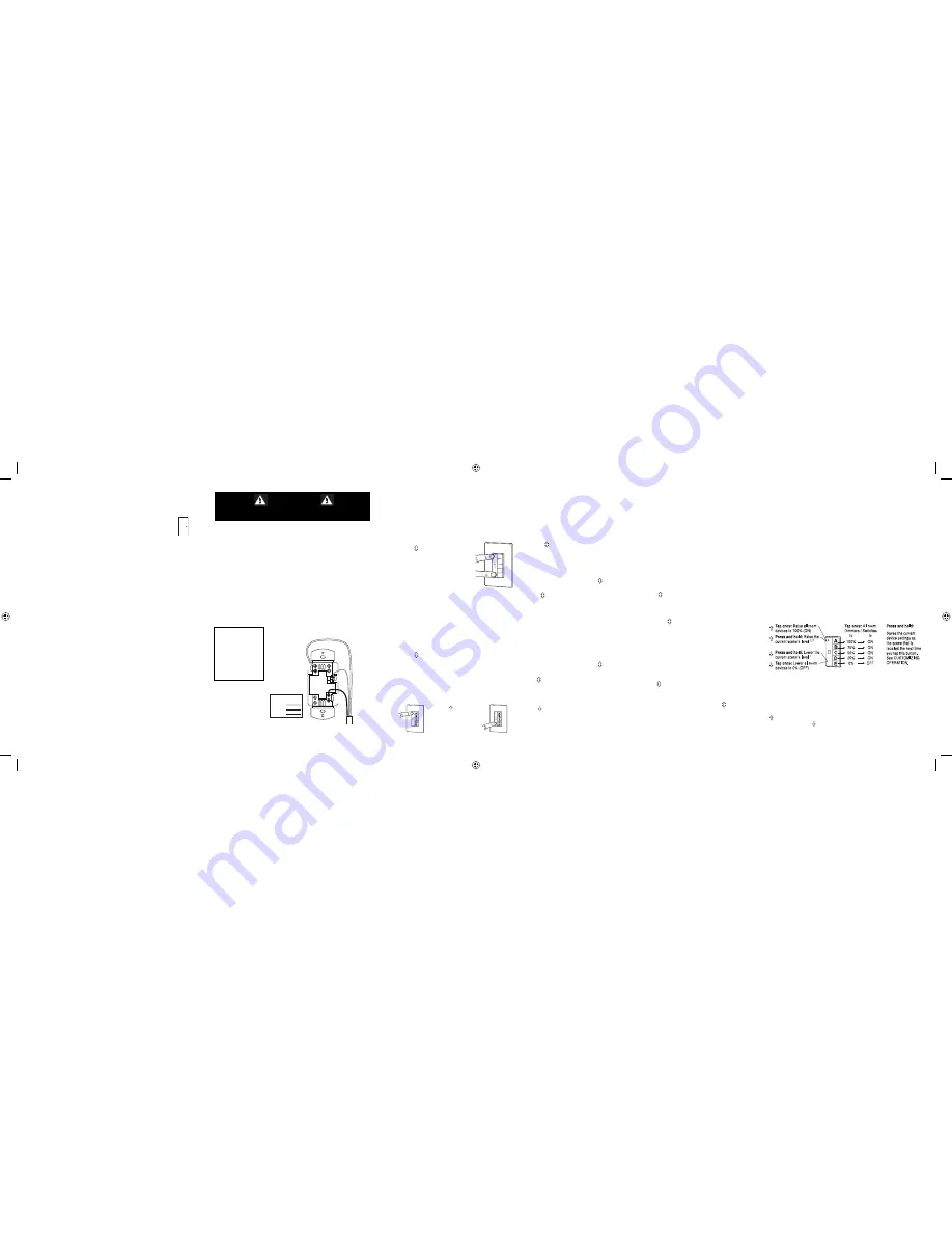
When you see
in the instructions,
firmly press and
hold both the top
and bottom of
the paddle until
the LED changes
(about 2 seconds).
When you
see in
the instructions, touch
the top of the paddle
as directed.
When you see
in
the instructions, touch
the bottom of the
paddle as directed.
Paddle
Scene Buttons
3
CAUTION
TURN THE POWER OFF AT THE CIRCUIT BREAKER
BEFORE INSTALLING THE DIMMER.
INSTALLATION
For ease of installation, manufacturer recommends use of a deep wall box. The
device is equipped with flying leads to simplify installation, however, if desired,
they may be removed by loosening the screw terminals.
1. Disconnect power to circuit by turning circuit breaker OFF before installation.
2. Remove existing wall plate and switch.
3. Strip existing wires 1/2”. If two wires will be connected to the same terminal
on a Miro device, both wires must be the same gauge (12AWG or 14AWG).
4. Wire the LINE (black), NEUTRAL (white) and GND supply wires to the
correspondingly marked screw terminals, according to the wiring diagram.
5. Attach the wall plate.
6. Switch the circuit breaker back ON.
LINE
GND
Supply
Wires
NEUT
Wire Legend
Ground
Line
Neutral
INSTALL IN
COMPLIANCE WITH
ALL APPLICABLE
CODES & STANDARDS.
Failure to follow these
instructions may cause
personal injury or
equipment damage.
ii_DRD6v2 07479r2.indd 6-10
ii_DRD6v2 07479r2.indd 6-10
9/24/2007 4:17:30 PM
9/24/2007 4:17:30 PM


