14
the slots so that the centerline of the hinges are flush with
the leading edge. If the hinges cannot be inserted deeply
enough, use a modeling knife to carefully cut the hinge
slots deeper.
❑
4)
With each of the hinges centered, apply 3-4 drops
of Kwik Bond Thin C/A to the joint where the hinges and
the elevator meet. Allow a few seconds between drops
for the C/A to wick into the hinges, then turn the elevator
over and repeat this procedure on the other side. Let the
C/A dry for about 10 minutes before proceeding. See
photo # 14 below.
❑
5)
Slide the elevator and its hinges into the precut
hinge slots in the trailing edge of the stabilizer. Adjust
the elevator so that the tips of the elevator are even with
the tips of the stabilizer.
❑
6)
While holding the elevator tight against the sta-
bilizer, rotate the elevator down about 45º. Apply 3-4
drops of Kwik Bond Thin C/A to the exposed area of each
hinge. Turn the fuselage over and repeat for the other
side of the hinges. Allow the C/A to dry for about 10
minutes. Once the C/A dries, the elevator may be stiff
and difficult to move. This is normal. Gently move it up
and down about five to ten times to free it up.
Photo # 14
❑
7)
Using a modeling knife, remove the covering
from over the predrilled hole in the leading edge of the
rudder. The hole is 1/16" in diameter and is located 1/2"
up from the bottom of the rudder.
❑
8)
Using a modeling knife, carefully cut a shallow
groove in the leading edge from the base of the hole down
to the bottom of the rudder. See figure # 6 below.
INSTALLING THE
TAIL WHEEL ASSEMBLY
Figure # 6
❑
9)
Test fit the tail wheel wire into the hole and
groove. When properly aligned, the wire should rest
within the groove and the outer surface of the wire should
be flush with the leading edge of the rudder.
❑
10) When satisfied with the fit, remove the tail wheel
wire. Using 220 grit sandpaper, carefully roughen the
gluing surface of the wire.
❑
11)
Mix a small quantity of Kwik Bond 5 Minute
Epoxy. Pack epoxy into the hole and the groove and
push the tail wheel wire firmly into place. Remove any
excess epoxy using a paper towel and rubbing alcohol.
Allow the epoxy to fully cure before proceeding. See
photo # 15 below.
Photo # 15
HINGING THE RUDDER
❑
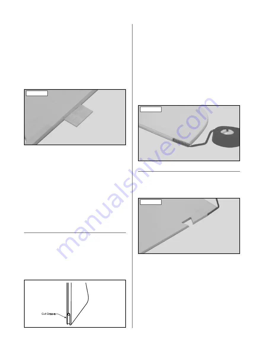
12) Using a modeling knife, carefully remove the
covering from over the precut notch in the leading edge
of the rudder. The notch is located 1-1/4" up from the
bottom of the rudder. See photo # 16 below.
❑
13) Locate the two precut hinge slots in the trailing
edge of the vertical stabilizer and the leading edge of the
rudder.
❑
14) Using a modeling knife, carefully remove any
excess covering material from over each of the slots.
❑
15) Test fit the C/A hinges into the hinge slots in
the rudder. Each hinge should be inserted far enough into
the slots so that the centerline of the hinges are flush with
the leading edge. If the hinges cannot be inserted deeply
enough, use a modeling knife to carefully cut the hinge
slots deeper.
Photo # 16


