7
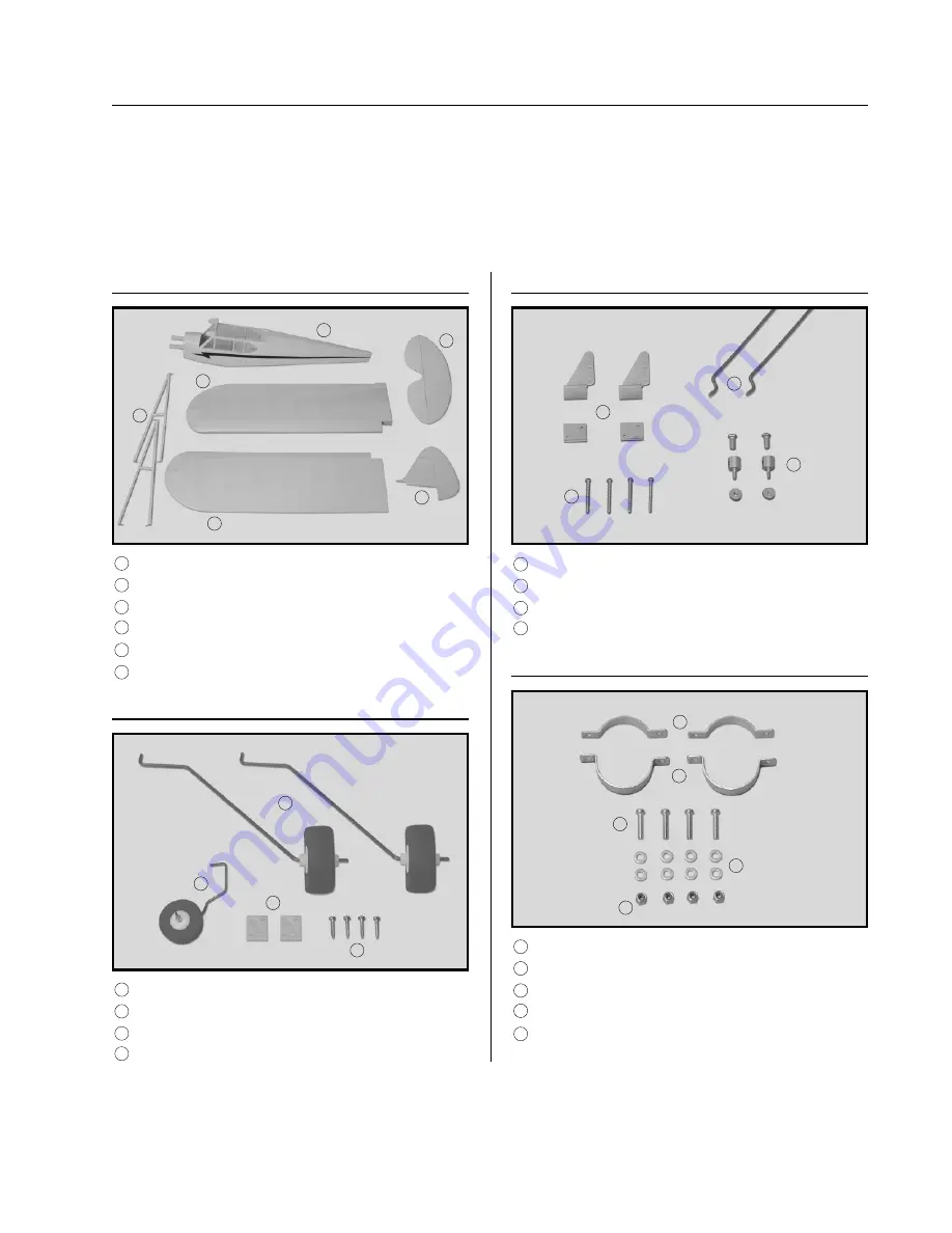
We have organized the parts as they come out of the box for easier identification during assembly. Each photo below
represents the parts that are required in a main section of the assembly process. Before you begin assembly, group the
parts like we show. This will ensure that you have all of the parts before you begin assembly and it will also help you
become familiar with each part. The corresponding part number is listed first, then the quantity of that particular part,
along with a short description of the part. As you proceed through assembly, you will notice the same part number
listed next to a particular part necessary for that step. If you have any questions as to what that part might be, refer back
to this section.
KIT CONTENTS
AIRFRAME ASSEMBLIES
PUSHROD ASSEMBLIES
❑
{1} Fuselage w/Pushrod Housings
❑
{1} Right Wing Half
❑
{1} Left Wing Half
❑
{1} Horizontal Stabilizer w/Elevator & Hinges
❑
{1} Vertical Stabilizer w/Rudder & Hinges
❑
{2} Wing Strut Assemblies (1 left & 1 right)
1
2
3
4
5
6
❑
{2} 1.5mm x 385mm Pushrod Wires w/Z-Bends
❑
{2} Nylon Control Horns w/Backplates
❑
{2} 2mm x 12mm Machine Screws
❑
{2} Adjustable Servo Connector Assemblies
11
12
13
14
LANDING GEAR ASSEMBLIES
❑
{2} Main Landing Gear Wires w/Wheels
❑
{1} Tail Wheel Assembly w/Wheel
❑
{2} Nylon Landing Gear Straps
❑
{4} 2mm x 10mm Wood Screws
7
8
9
10
MOTOR MOUNT ASSEMBLIES
❑
{2} Aluminum Motor Mount Clamps - Short
❑
{2} Aluminum Motor Mount Clamps - Tall
❑
{4} 3mm x 14mm Machine Screws
❑
{8} 3mm Flat Washers
❑
{4} 3mm Nylon Insert Nuts
15
16
17
18
19
1
2
3
4
5
6
7
8
9
10
11
12
13
14
15
16
17
18
19


