14
❑
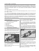
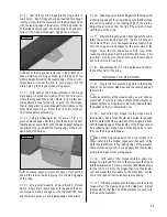
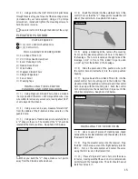
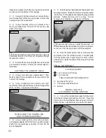
10) Carefully slide one 45mm diameter wheel onto
the axle, followed by a second 3mm nylon wheel retainer.
Align the predrilled hole in the outside of the wheel pant
and push it over the end of the axle.
See figure # 5 below.
Figure # 5
❑
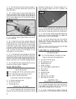
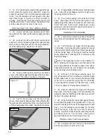
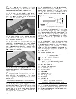
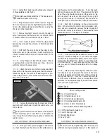
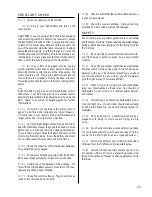
11) Secure the wheel pant to the landing gear wire
using one prebent aluminum wheel pant mount and two
2mm x 6mm wood screws. Thread the screws into the
predrilled holes and tighten both of them firmly to hold
the wheel pant in place.
See photo # 17 below.
Photo # 17
☛
A small piece of plywood has been preglued to the
inside surface of the wheel pant for the wood screws to
thread into.
❑
12) Repeat steps # 9 thru # 11 to install the second
wheel and wheel pant assembly.
TOOLS AND SUPPLIES REQUIRED
SERVO INSTALLATION
❑
# 0 Phillips Head Screwdriver
❑
Excel Modeling Knife
❑
Electric or Hand Drill
❑
1/16" Drill Bit
INSTALLING THE SERVOS
❑
1) Using a # 0 phillips screwdriver, remove the two
wood screws that hold the canopy deck in place. Remove
the canopy deck from the fuselage and set it aside.
❑
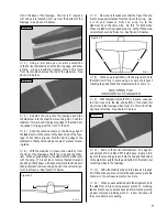
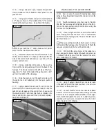
2) Locate the three servos you intend to use for the
elevator, rudder and aileron controls. Carefully install the
rubber grommets and brass collets onto each of the servo
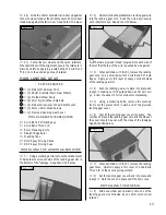
mounting lugs. For proper vibration reduction, the brass
collets should be inserted into the rubber grommets with
the flanges facing the bottom of the servo mounting lugs.
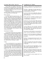
See figure # 6 below.
❑
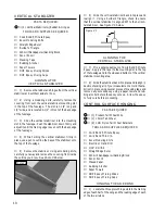
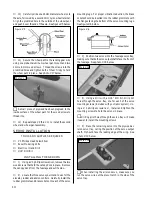
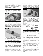
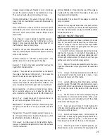
3) Position two servos into the fuselage servo tray,
making sure that both servo output shafts face the front of
the fuselage.
See photo # 18 below.
Figure # 6
Photo # 18
❑
4) Using a drill with a 1/16" drill bit, drill pilot
holes through the servo tray, one for each of the servo
mounting screws (included with your radio system). Us-
ing a # 0 phillips screwdriver, install and tighten the
mounting screws to hold the servos in place.
☛
Drilling pilot holes through the servo tray will make
it easier to install the mounting screws.
❑
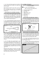
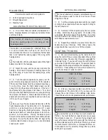
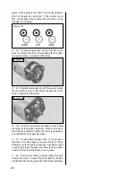
5) Place the remaining servo into the plywood ai-
leron servo tray, noting the position of the servo output
shaft. It should face the leading edge of the wing.
See
photo # 19 below.
Photo # 19
☛
When installing the aileron servo, make sure you
run the servo wire out the precut notch in the side of the
servo tray.


