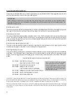
18
❑
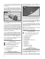
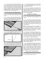
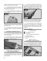
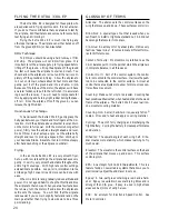
14) Remove the masking tape from the rudder and
double check that both the rudder and the rudder servo
are still centered.
☛
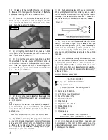
To adjust the center-trim of the rudder, use a pair of
pliers to carefully open or close the "V" in the pushrod
wire. Doing this will effectively lengthen or shorten the
pushrod wire.
ADJUSTING THE RUDDER PUSHROD
❑
15) With your radio system plugged in and turned
on, check the direction the rudder control surface moves
and the amount of control deflection. To do this push
right on the rudder control stick. The rudder should move
right. If it does not, flip the servo reversing switch on
your transmitter to change the direction.
❑
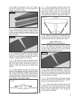
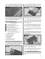
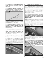
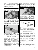
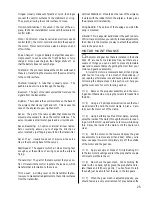
16) Push right completely on the rudder control stick.
While holding the control stick completely right, use a ruler
and measure the amount the trailing edge of the rudder
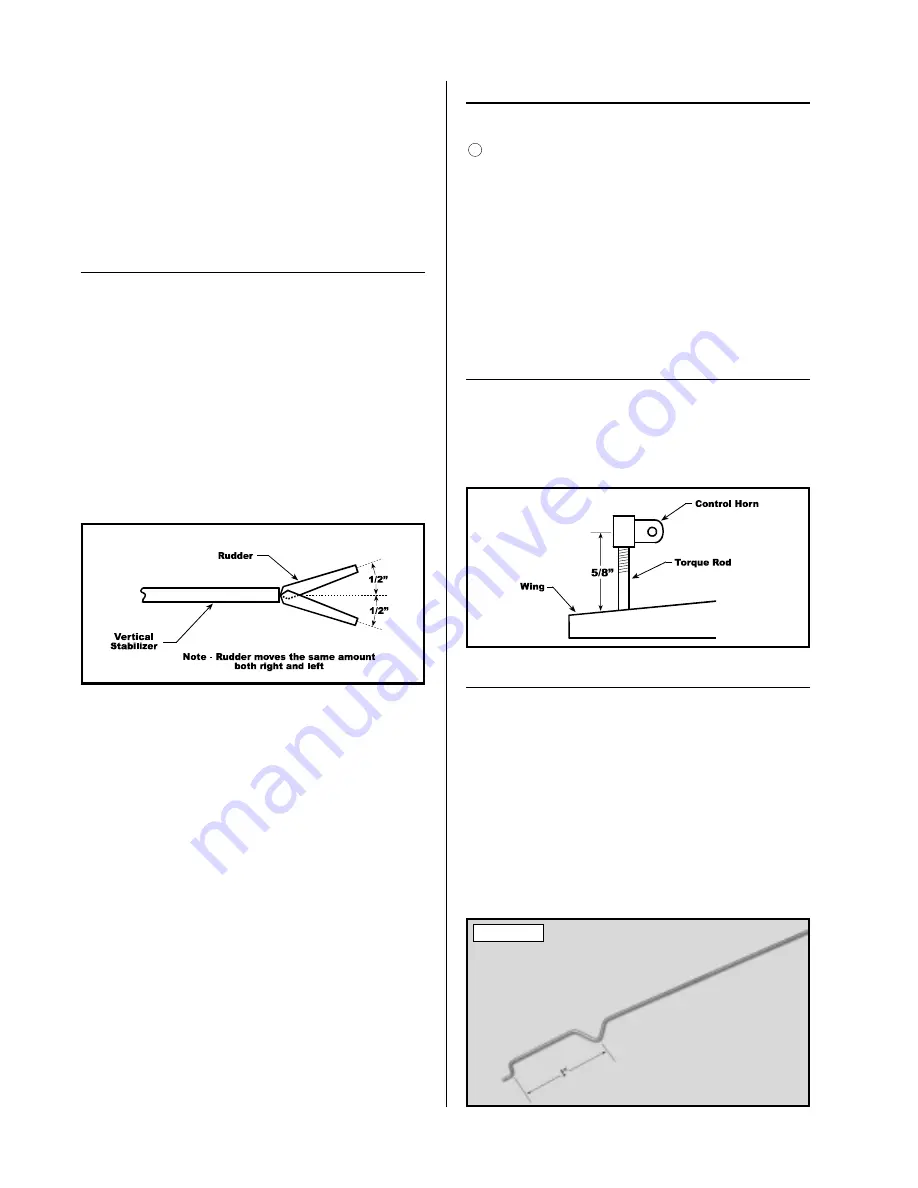
moves right. This measurement should be 1/2" measured
at the widest point of the rudder.
See figure # 8 below.
Figure # 8
❑
17) If the control surface deflection is more or less
than 1/2" it must be changed. If your radio is equipped
with End Point Adjustments (EPA), make those adjust-
ments using the transmitter. (Refer to your radio guide
for further details.) If your radio does not have this fea-
ture, you can still make the adjustments to the pushrod
manually.
❑
18) If the rudder is moving
more
than 1/2", move
the Z-bend in one hole toward the center of the servo horn
to decrease the control deflection. If the rudder is mov-
ing
less
than 1/2", move the Z-bend out one hole from the
center of the servo horn to increase the control deflection.
When adjusted properly, the rudder should move 1/2" both
right and left.
☛
Double check that both the elevator and the rudder
pushrods move without binding. If there is any binding
present, use a pair of pliers to make very small bends in
the pushrod wires until they move smoothly.
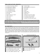
PARTS REQUIRED
TOOLS AND SUPPLIES REQUIRED
AILERON LINKAGE
❑
# 0 Phillips Head Screwdriver
❑
Needle Nose Pliers
❑
Wire Cutters
❑
Magnum Z-Bend Pliers
❑
Straight Edge Ruler
❑
Pen or Pencil
❑
Masking Tape
❑
{2} 1mm x 110mm Pushrod Wires
6
ADJUSTING THE CONTROL HORNS
❑
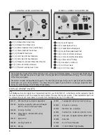
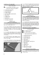
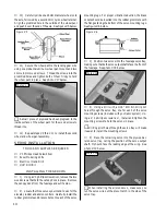
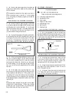
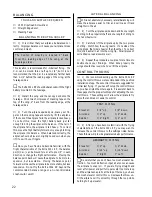
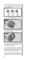
1) Two nylon adjustable control horns have been
partially threaded onto the two aileron torque rods. Thread
the control horns into their final positions. The centerline
of each control horn should be 5/8" up from the top of the
wing.
See figure # 9 below.
Figure # 9
INSTALLING THE AILERON LINKAGE
❑
2) Using Magnum Z-Bend Pliers, make a Z-bend
in only one end of each of the two 1mm x 110mm push-
rod wires. Use wire cutters to remove any excess wire,
leaving about 3/16" of wire beyond the Z-bends.
❑
3) Using a ruler and a pen, measure forward 1" from
the middle of the Z-bend and draw a mark. Do this on
both of the pushrod wires.
❑
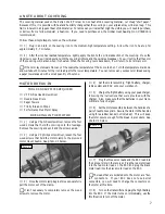
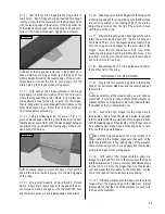
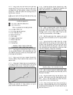
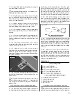
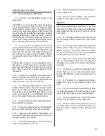
4) Using a pair of needle nose pliers, carefully bend
a "V" shape into each of the two pushrod wires at the
marks you drew.
See photo # 29 below.
Photo # 29

