7
The covering material used on the Extra 330L EP is real iron-on heat shrink covering material, not cheap "shelf paper."
Because of this, it is possible with heat and humidity changes that the covering on your airplane may wrinkle or sag. This
trait is inherent in all types of heat shrink material. To remove any wrinkles that might be visible you will need to purchase,
or borrow from a fellow modeler, a heat iron. If you need to purchase one, the
Global Heat Sealing Iron # 360900
is
recommended.
Follow these simple steps to remove the wrinkles:
❑
1) Plug in and turn on the sealing iron to the medium-high temperature setting. Allow the iron to heat up for
approximately 5 - 7 minutes.
❑
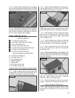
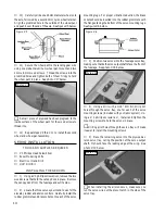
2) After the iron has reached temperature, lightly apply the iron to the wrinkled section of the covering. Move the
iron slowly over the wrinkled section until the covering tightens and the wrinkles disappear. You will notice that the color
of the covering will darken when it is heated. When the covering cools back down, it will return to its normal color.
☛
If the color layer smears from any of the seams the temperature of the iron is too hot. Turn the temperature dial down
and wait about 5 minutes for the iron to adjust to the lower temperature. You can remove any excess color streaks using
a paper towel soaked with a small quantity of Acetone.
MOTOR BREAK-IN
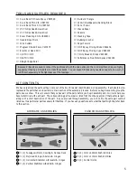
TOOLS AND SUPPLIES REQUIRED
BREAKING IN THE MOTOR
❑
# 0 Phillips Head Screwdriver
❑
Needle Nose Pliers
❑
Paper Towels
❑
Trinity Break-In Drops
❑
Performance Plus Motor Spray
❑
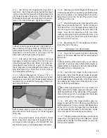
1) Using a # 0 phillips screwdriver, remove the four
wood screws that hold the cowling onto the fuselage.
Remove the cowling and set it and the screws aside.
❑
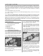
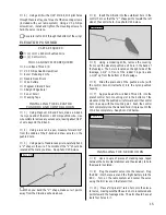
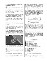
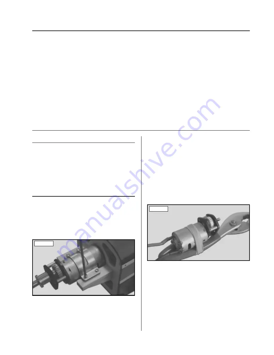
2) Using a # 0 phillips screwdriver, loosen the four
wood screws that hold the motor clamp to the plywood
motor mount beams.
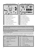
See photo # 1 below.
❑
3) Once the motor clamp begins to loosen, carefully
pull the motor out of the clamp.
☛
It isn't necessary to completely remove the wood
screws to remove the motor.
Photo # 1
❑
4) Set the motor assembly, flight battery, charger,
radio system and ESC onto your workbench.
❑
5) Charge the flight battery using your peak charger,
following the instructions that were provided with the
charger. Also, make sure that the batteries in your trans-
mitter are fully charged.
❑
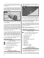
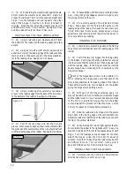
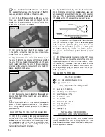
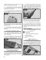
6) Set the motor assembly between the handles of a
pair of needle nose pliers. Secure the motor to the handles
using three rubber bands (not included). This will keep
the motor secure enough for the break-in procedure.
See
photo # 2 below.
Photo # 2
❑
7) Plug the three servo leads and the ESC lead into
their proper slots in the receiver. Plug the red motor lead
into the red motor lead on the ESC and plug the black
motor lead into the black motor lead on the ESC.
☛
The leads that are soldered onto the motor are "bul-
let" connectors. If your ESC does not use bullet
connectors, you will need to change the connectors on
the motor at this time.
❑
8) Turn on the transmitter and plug the flight battery
into the ESC. If the motor turns on immediately, use the
throttle stick to turn off the motor.
A NOTE ABOUT COVERING


