8
❑
9) With the motor turned off, test the operation of
the three servos. Each servo should move when you move
the control sticks.
❑
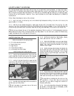
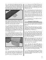
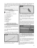
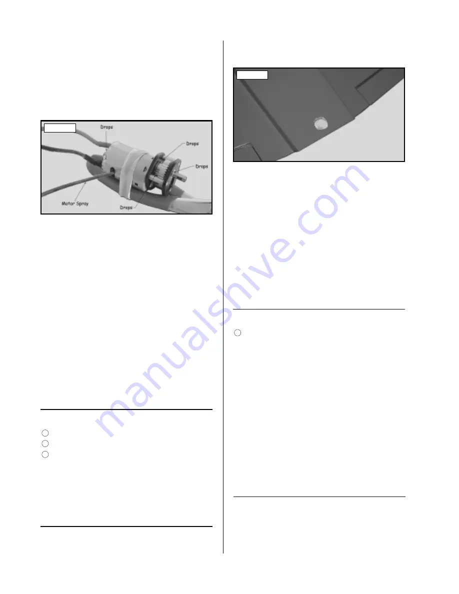
10) Carefully spray a couple of light sprays of Per-
formance Plus Motor Spray inside the motor openings and
apply a small drop of Trinity Break-In Drops onto each of
the two motor bushings and onto the gear box bearings.
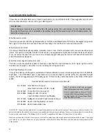
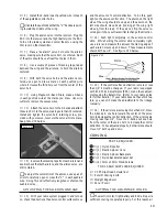
See photo # 3 below.
Photo # 3
❑
11) Using a couple of paper towels, wipe off the
excess motor spray.
❑
12) Slowly turn on the motor using the transmitter
throttle control stick. Position the stick to about 1/3 throttle
and let the motor run. While the motor is running, apply
a light spray of motor spray inside the motor openings
once every minute, followed by a small drop of Break-In
Drops on each of the motor bushings and gear box bear-
ings. Continue to do this until the battery is fully
discharged (i.e., the motor stops).
❑
13) After the battery has discharged and the motor
has stopped, spray motor spray through the motor open-
ings until the fluid runs clear. Apply a couple of drops of
Break-In Drops to the motor bushings and gear box bear-
ings and wipe away all of the excess using paper towels.
❑
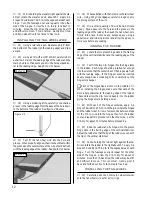
14) Reinstall the motor assembly and the cowling.
Reverse the removal steps for installation.
PARTS REQUIRED
TOOLS AND SUPPLIES REQUIRED
WING MOUNTING
❑
# 1 Phillips Head Screwdriver
❑
Excel Modeling Knife
❑
Straight Edge Ruler
1
2
23
MOUNTING THE WING
❑
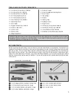
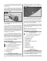
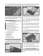
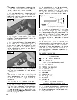
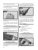
1) Using a modeling knife, cut away the covering
material from over the predrilled wing hold down hole in
the bottom of the belly pan. The hole is located 1/2" in
front of the trailing edge and is 7/16" in diameter.
See
photo # 4 below.
Photo # 4
❑
2) Using a modeling knife, cut away the covering
material from over the 1/8" diameter hole located on the
top of the wing, directly above the hole in the belly pan.
❑
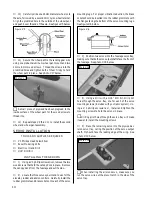
3) Place the wing into the wing saddle, making sure
that the dowel in the leading edge of the wing engages the
predrilled hole in the forward bulkhead.
❑
4) Line up the trailing edge of the wing with the
fuselage and install the wing using the 3mm x 15mm
machine screw. Tighten the machine screw firmly using
a # 1 phillips screwdriver.
☛
The plywood wing hold down block has threads
tapped into it for the bolt to thread into.
PARTS REQUIRED
TOOLS AND SUPPLIES REQUIRED
HORIZONTAL STABILIZER
❑
Kwik Bond 5 Minute Epoxy
❑
Excel Modeling Knife
❑
Straight Edge Ruler
❑
Builder's Triangle
❑
220 Grit Sandpaper w/Sanding Block
❑
Pen or Pencil
❑
Masking Tape
❑
Rubbing Alcohol
❑
Paper Towels
❑
NHP Epoxy Mixing Sticks
❑
NHP Epoxy Mixing Cups
❑
{1} Horizontal Stabilizer w/Elevator & Hinges
3
❑
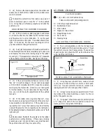
1) Remove the elevator and hinges from the hori-
zontal stabilizer and set them aside for now. Remove the
wing from the fuselage and set it aside, also.
❑
2) Using a modeling knife, carefully remove the
covering from over the horizontal stabilizer mounting
ALIGNING THE
HORIZONTAL STABILIZER
❑
{1} Fuselage w/Motor, Cowling & Canopy Deck
❑
{1} Prejoined Wing w/Ailerons & Hinges
❑
{1} 3mm x 15mm Machine Screw


