11
❑
5)
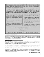
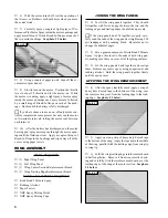
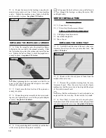
Install the servo tray into the fuselage. To align
the servo tray properly, the back edges of the servo tray
mounting sides should be pushed up against the front of
the aluminum wing mounting tube, and the tops of the
servo tray mounting sides should be pushed up against
the bottom of the wing saddle. See photo # 17 below.
❑
6)
When satisfied with the alignment, press the
servo tray sides firmly into place to secure the tray into
the fuselage.
INSTALLING THE SERVOS
❑
7)
Install the rubber grommets and brass collets onto
each of the servo mounting lugs.
❑
8)
Test fit your two micro servos into the servo tray.
If necessary, use a modeling knife to enlarge the hole in
the servo tray to accommodate the two servos. The ser-
vos should fit tightly in the servo tray.
☛
Both of the servos' output shafts should face toward
the front of the fuselage.
❑
9)
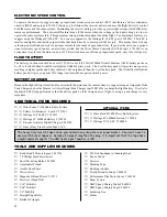
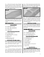
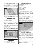
Mount the servos to the servo tray using the servo
mounting screws provided with your servos. Use the tip
of your modeling knife to make small pilot holes in the
reinforcement board. See photo # 18 below.
Photo # 17
Photo # 18
PUSHROD INSTALLATION
TOOLS AND SUPPLIES REQUIRED
ITEMS REQUIRED
❑
{2} Threaded Pushrod Wires
❑
{2} Nylon Control Horns w/Backplates
❑
{2} Nylon Clevises
❑
# 0 Phillips Head Screwdriver
❑
Modeling Knife
❑
Wire Cutters
❑
Magnum Z-Bend Pliers
❑
Electric or Hand Drill
❑
1/16" Drill Bit
❑
Straight Edge Ruler
❑
Pen or Pencil
INSTALLING THE CONTROL HORNS
❑
1)
Using a modeling knife, cut one thin slot through
the middle of each molded recess in both the elevator and
the rudder. Cut the slot large enough for the ends of the
control horns to pass through.
❑
2)
Push one control horn through each slot. The
end of the elevator control horn should be on the bottom
of the elevator and the end of the rudder control horn
should be on the left side of the rudder.
❑
3)
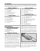
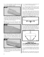
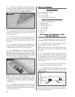
Making sure the flat portion of the backplates
face away from the control surfaces, push the backplates
over the ends of the control horns until you hear them
"click" into place. See photo # 19 below.
Photo # 19
INSTALLING THE PUSHRODS
❑
4)
Using a modeling knife, carefully cut out the rud-
der pushrod exit hole (the back of the molded fairing) in
the top of the fuselage. Make the cutout large enough for
the pushrod wire to pass through easily.
❑
5)
Plug in your receiver, ESC, flight battery and
elevator and rudder servos. Turn on the radio system
and center both of the servos using the trim levers on the
transmitter.
❑
6)
Thread one nylon clevis onto each of the two
threaded pushrod wires. Thread the clevises on far enough
to leave room for adjustments later.
☛
Don't push the backplates too far down over the con-
trol horns or you might crush the foam.


