12
❑
8)
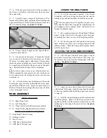
Place a "single arm" servo horn onto the eleva-
tor servo, making sure that the servo horn is centered and
points toward the fuselage side. The arm should have at
least three holes in it.
❑
9)
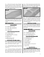
With both the servo horn and the elevator cen-
tered, use a pen and draw a mark on the pushrod wire
where it crosses the third hole out from the center of the
servo horn.
❑
10)
Unsnap the clevis and remove the pushrod wire
from the fuselage. Using Magnum Z-Bend Pliers, make a
Z-Bend in the pushrod wire at the mark you drew.
❑
11)
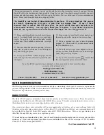
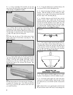
Slide the pushrod wire back into place and snap
the clevis into the control horn. Attach the servo horn to
the Z-Bend, then attach the servo horn to the servo, mak-
ing sure it's centered. Install and tighten the servo horn
retaining screw, provided with your servo, to secure the
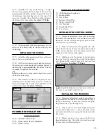
servo arm into place. See photo # 21 below.
FINAL ASSEMBLY
TOOLS AND SUPPLIES REQUIRED
❑
# 0 Phillips Head Screwdriver
❑
Modeling Knife
❑
Electric or Hand Drill
❑
1/16" Drill Bit
❑
5/64" Drill Bit
❑
Pen or Pencil
❑
Scissors
ITEMS REQUIRED
❑
{1} Molded Clear Canopy
❑
{1} Velcro Strip
❑
{1} Decal Sheet
❑
{2} 2mm x 5mm Wood Screws
INSTALLING THE RECEIVER, FLIGHT
BATTERY AND ESC
❑
1)
Using a modeling knife, cut out the on-off switch
and arming switch holes in the left side of the fuselage.
❑
2)
Install the on-off switch and arming switch us-
ing the hardware provided with your ESC.
☛
If your ESC does not come with mounting screws,
use # 2 sheet metal screws and # 2 flat washers to install
the switch.
❑
3)
Using a pair of scissors, cut the piece of Velcro
in half. Using one piece of Velcro, mount the receiver to
the fuselage floor in front of the servo tray. Uncoil the
antenna and feed it out the elevator pushrod exit hole in
the back of the fuselage. Use a piece of Scotch tape to
hold it in place.
❑
4)
If you haven't already done so, connect the mo-
tor leads from your ESC to the tabs on the motor.
❑
5)
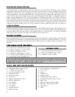
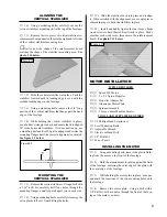
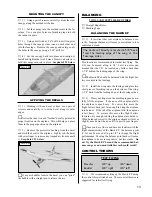
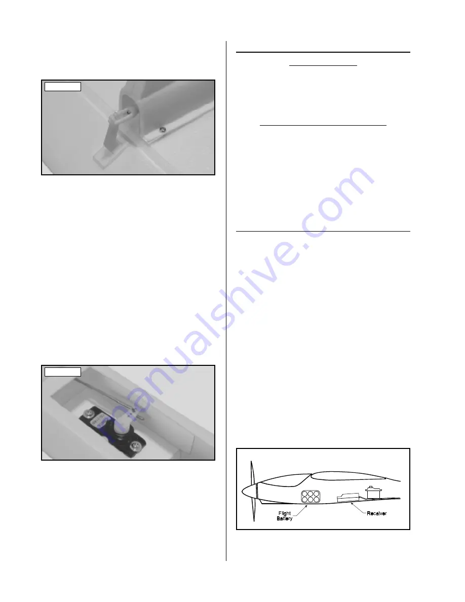
Mount the battery onto the fuselage floor, in front
of the receiver, using the second piece of Velcro. See
figure # 4 below.
❑
7)
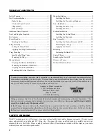
Slide one of the pushrod wires up through the
back of the fuselage, making sure that the wire enters the
servo compartment above the servos. Snap the clevis into
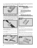
the elevator control horn. See photo # 20 below.
Photo # 20
Photo # 21
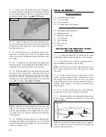
☛
You will have to enlarge the hole in the servo arm
using a 1/16" drill bit, so that the pushrod wire will fit
through; and, depending on the length of the servo horn,
you may have to cut it shorter so that it doesn't hit the side
of the fuselage.
❑
12) Install the rudder pushrod wire using the same
technique as with the elevator pushrod wire. The Z-Bend
should be installed into the third hole out from the center
of the servo horn as well.
Figure # 4
☛
The location of the battery shown above is approxi-
mate. You may have to move it fore or aft to balance the
airplane in the next section.


