9
❑
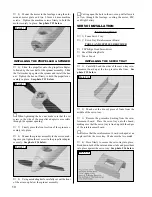
10) Using a modeling knife, carefully cut out the
vertical stabilizer mounting slot in the top of the fuselage.
❑
11)
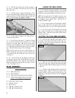
Remove the two pieces of vertical stabilizer re-
inforcement board and stick them to the right and left sides
of the vertical stabilizer mounting area.
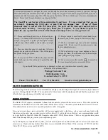
☛
Notice how the shape of the reinforcement board
matches the shape of the stabilizer mounting area. See
photo # 10 below.
❑
12) Slide the vertical stabilizer into place. Push the
stabilizer forward until its leading edge is even with the
molded leading edge in the fuselage.
❑
13) Using a modeling knife, remove the 1/4" long
portion of the vertical stabilizer that hangs past the back
edge of the fuselage.
❑
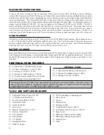
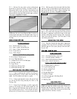
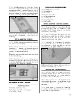
14) While holding the vertical stabilizer in place,
use a builder's triangle to check and ensure that it is aligned
90º to the horizontal stabilizer. If it does not line up, use
a modeling knife and/or 220 grit sandpaper and retrim the
mounting flanges until the correct alignment is achieved.
See figure # 3 below.
Figure # 3
❑
15) Remove the vertical stabilizer. Using a drill with
a 1/16" drill bit, carefully drill four holes through the
mounting flanges, equally spaced apart, two on each side.
❑
16) Using a modeling knife, carefully trim away the
extra plastic left over from drilling the holes.
ALIGNING THE
VERTICAL STABILIZER
Photo # 10
MOUNTING THE
VERTICAL STABILIZER
❑
17)
Slide the stabilizer back into place and realign
it. When satisfied with the alignment, use a couple pieces
of masking tape to hold the stabilizer in place.
❑
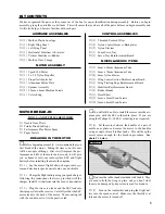
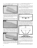
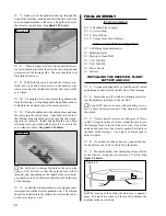
18)
Install and lightly tighten the four 1mm x 4mm
wood screws to hold the stabilizer firmly in place. Make
sure that each wood screw threads into the reinforcement
board. See photo # 11 below.
Photo # 11
MOTOR INSTALLATION
TOOLS AND SUPPLIES REQUIRED
❑
# 0 Phillips Head Screwdriver
❑
Excel Modeling Knife
❑
Adjustable Wrench
❑
Electric or Hand Drill
❑
1/8" Drill Bit
❑
Pen or Pencil
ITEMS REQUIRED
❑
{1} Speed 380 Motor
❑
{1} 5 x 2.5 Nylon Propeller
❑
{1} Propeller Adapter Set
❑
{1} Aluminum Motor Plate
❑
{1} Spinner Assembly
❑
{1} 2.5mm x 4mm Machine Screws
INSTALLING THE MOTOR
❑
1)
Using a modeling knife, remove the plastic flash-
ing from the seam on the front of the fuselage.
❑
2)
Hold the aluminum motor plate against the front
of the fuselage, centering the outer edge of the plate with
the outer edge of the fuselage.
❑
3)
While holding the motor plate in place, use a pen
and mark the locations of the two mounting holes onto
the fuselage.
❑
4)
Remove the motor plate. Using a drill with a
1/8" drill bit, drill two holes through the front of the fuse-
lage at the marks you drew.


