background image

pg.2

WB-200-IW-2-WHT Installation and Users Manual

PACKAGE CONTENTS

(1) WB-200-IW-2

(4) Mounting Screws
(3) Wire Nuts

REQUIRED WIRING

We recommend the use of 12/2C or 14/2C IN-DOOR building electrical wire to connect to the WB-200-IW-2.  All wiring should be 
performed by a licensed electrician .  Verify with your electrician that the building electrical wire run to the location of the WB-
200-IW-2 meets or exceeds 12/2C or 14/2C IN-DOOR.

TOOLS REQUIRED

• Phillips head and flat blade screw driver
• Wire-stripper
• Needle Nose Pliers
• Electrical Outlet Tester

IMPORTANT: BEFORE YOU BEGIN!

• Check with your local building jurisdiction as to permit, license or code requirements for installing wire or outlets within a wall. 

Some municipalities require an electrical inspection for modification of electrical work. We recommend all modifications or 
alterations of existing or new electrical work to be inspected by a licensed electrical inspector.

• Install this product to meet National Electrical Code and/or State and Local Building Code requirements for installing electrical building 

wire and outlets as a single EXTENSION CIRCUIT, without modification or alteration to the building electrical circuit/wiring system. 
Installation Code Compliancy is the responsibility of user and or installer, and not of the Manufacturer or its agents.

• Manufacturer is not liable for damages due to improper installation methods not followed herein or as required by national 

electrical or local building code. It is strongly recommended that a qualified professional should install this product. The WB-
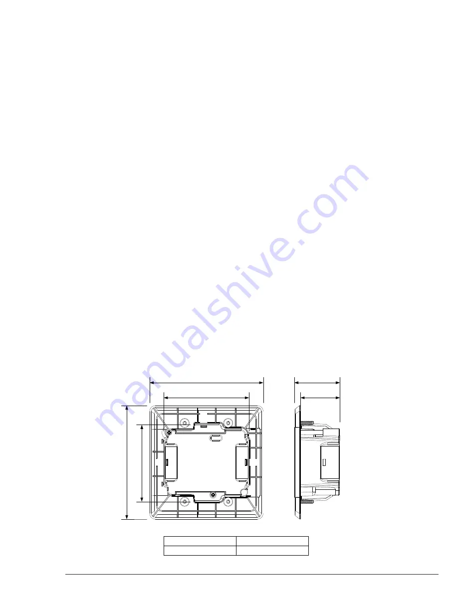
200-IW-2 was designed for New Construction and fits most boxes available.  Fitting into Retro boxes is limited, however these 
types of boxes can be used if the design of the box is greater than the internal dimensions indicated in the Unit Dimensions 
diagram.

3.

2i

n.

1.6in.

3.5in.

4.

7i

n.

4.7in.

2.2in.

External Dimensions
Internal Dimensions

4.7" H x 4.7" W x 2.3" D
3.2" H x 3.5" W x 1.6" D

Summary of Contents for WB-200-IW-2

Page 1: ... to improve picture and sound quality Child Safety Shutters Prevents unwanted contact with outlets when exposed WELCOME TO WATTBOX WattBox power products are designed specifically to provide customers with advanced protection for their valuable electronics and Custom Integrators with maximum flexibility for installation Rest assured that WattBox products will deliver the protection and safety for ...

Page 2: ...work to be inspected by a licensed electrical inspector Install this product to meet National Electrical Code and or State and Local Building Code requirements for installing electrical building wire and outlets as a single EXTENSION CIRCUIT without modification or alteration to the building electrical circuit wiring system Installation Code Compliancy is the responsibility of user and or installe...

Page 3: ...n for the WB 200 IW 2 2 Run a minimum of 14 2C IN DOOR building electrical wire through the rear opening of the outlet box Leave about 3 inches of wire extending out of the box 3 Verify that the AC circuit to the location is OFF 4 Strip 1 4 inch off each of the three ROMEX wires and three wires on the rear of the WB 200 IW 2 5 Using wire nuts connect the three electrical wires to the WB 200 IW 2 G...

Page 4: ...ired be sure the service technician is a licensed electrician Upon completion of any service ask the electrician to perform safety checks to determine that the product is in proper operating condition prior to use If you have any difficulty operating the WB 200 IW 2 refer to the warranty information contained in this owner s manual WARNING LIQUID AVOIDING ELECTRICAL SHOCKS Do not operate the Compo...

Page 5: ...er has been tripped Reset the circuit breaker If breaker continues to trip the connected devices may be drawing too much current or there is a short in the wiring Unplug 1 device at a time and reset the breaker Check the in wall wiring for a short Protected LED turns off and connected devices not receiving power WattBox internal surge protecting is inoperative indicating that multiple over voltage...

Page 6: ...n 500V Joule Rating 1080 Joules Surge Component Ceramic Encased MOV Protection Modes L N L G N G Peak Impulse Current 72 000A Disconnect Circuitry Yes Thermal Fuse Yes EMI RFI Noise Filtration All Outlets 53 dB 150kHz to 100MHz UL Certifications UL 498 UL 1449 Dimensions External 4 7 H x 4 7 W x 2 3 D Dimensions Internal 3 2 H x 3 5 W x 1 6 D Connected Equipment Warranty 5 000 SPECIFICATIONS ...

Page 7: ...ons relative to its surge protection capability and under all of the circumstances failed to protect your connected equipment THIS POLICY IS SUBJECT TO THE CONDITIONS BELOW 1 PROOF OF PURCHASE REQUIRED SnapAV s connected equipment policy extends to the original purchaser of the SnapAV product only and is non transferable Original purchase receipts must accompany any product return or claim for con...

Page 8: ...osts or expenses arising out of reprogramming or loss of programming and or data shipping charges or fees service calls loss or damage occasioned by fire theft flood wind accident abuse or misuse and products subject to manufacturer s recall or similar event 8 DISPUTE RESOLUTION Any controversy or claim arising out of or relating to SnapAV Surge Protector Equipment Policy or the alleged breach the...

Reviews: