


WB-200-IW-2-WHT Installation and Users Manual
pg.3
© 2012 Wattbox
™
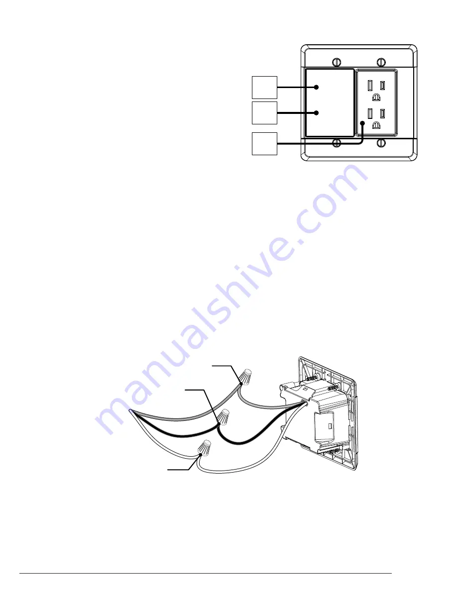
FRONT PANEL
INSTALLATION
1. Grounded Indicator LED
Green: WattBox Power Conditioner is grounded.
Off: Incoming AC outlet is not grounded and requires
inspection by an electrician.
2. Protection Indicator LED
Green: WattBox is powered on and outlets are protected.
Off: WattBox is not powered on, or the Surge Protection
circuitry has engaged, removing power from the outlets.
3. Outlets (Always On)
! Important Note: Before beginning the installation, turn the AC circuit to the location for the WB-200-IW-2 OFF.
Connecting while power is present is not recommended and can cause an unsafe condition.
1. Install a Double Gang outlet box (not included) in the desired location for the WB-200-IW-2.
2. Run a minimum of 14/2C IN-DOOR building electrical wire through the rear opening of the outlet box. Leave about 3 inches
of wire extending out of the box.
3. Verify that the AC circuit to the location is OFF.
4. Strip 1/4 -inch off each of the three ROMEX® wires and three wires on the rear of the WB-200-IW-2.
5. Using wire nuts, connect the three electrical wires to the WB-200-IW-2.
Green: Ground
Black: Line – Hot
White: Neutral
6. Push excess electrical wire back through the rear opening of the BLUE workbox and make sure to have the wire nuts all the
way into the back.
7. Place the WB-200-IW-2 into the workbox and screw securely into place with the supplied screws.
8. Turn the AC circuit ON; the Grounded and Protected LEDs will illuminate GREEN.
PROTECTED
GROUNDED
1
2
3
Note: This wire may be gray or bare wire on the electrical wires.
WB-200-IW-2
Wire from Wall
Green (Ground)
Black (Line - Hot)
White (Neutral)


