pg.2
WB-UPS-1100/1500/2000 Owner’s Manual
PACKAGE CONTENTS
(1) WB-UPS
(1) Owner’s manual
(1) Detachable power cord
(1) USB cable
(2) Upright mounting bases
(4) Rack mounting brackets
(8) Mounting bracket screws
(1) compact disc
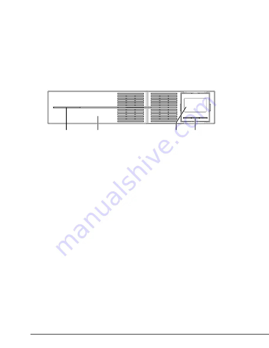
FRONT PANEL
1
2
4
3
1. Power LED – Illuminates solid blue when the UPS is powered on.
2. Removable Battery Cover – Snap the cover off to access the batteries for connection or replacement.
3. LCD Screen – Used for monitoring and setup of UPS software features.
4. LCD Control Buttons – Used for turning the UPS on and off, navigation and selection in menus, and muting alarm tones.
REAR PANEL (SEE DIAGRAMS ON OPPOSITE PAGE)
1. Circuit Breaker – Resetting circuit breaker that trips out the unit when over-amperage conditions occur.
2. EPO (Emergency Power Off) – Two-pin terminal for turning the UPS on (pins connected) and off (pins separated). Leave the jumper in place if
not required.
3. USB Port – Connect an automation system or a computer to control and monitor UPS operation through management software.
4. SNMP Card Slot – Remove the cover to install the optional UPS SNMP Card (not included).
5. Controlled Outlets – Non-critical load outlets that are protected and can be programmed to turn off when the battery level reduces to a set
percentage.
6. Uncontrolled Outlets – Critical load outlets that remain on until the UPS battery is depleted.
7. Ground Lug – Ground post for bonding equipment.
8. Power Inlet – Inlet power cord that connects to the supply outlet.
9. RS-232 Port – Connect an automation system or a computer to control and monitor UPS operation through management software.


