background image

pg.6

WB-UPS-1100/1500/2000 Owner’s Manual

SNMP CARD (SOLD SEPARATELY)

The SNMP card extends communication from the UPS to computers on the network running UPS software. Setup instructions and software are 

included with the card.

SNMP Card Installation

1.  Turn the UPS off (Standby mode) and disconnect the power cord.

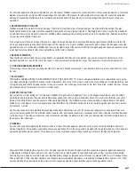
2.  Remove the SNMP card slot cover.

3.  Insert the SNMP card into the slot and secure using the panel cover screws.

4.  Connect the SNMP card to the LAN, then power the UPS on. Installation is complete. See the instructions included with the SNMP card for 

setup and use.

20A, 120Vac

Remove and insert card

DISCONNECT UPS FROM POWER!

X

BASIC OPERATION (FRONT PANEL BUTTONS)

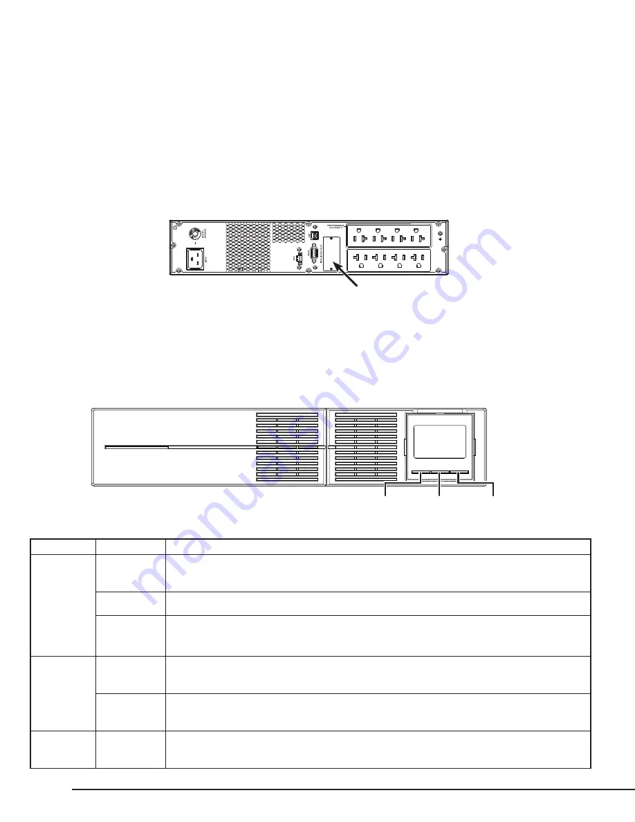
When the unit is plugged into a power outlet, the front panel LCD screen will illuminate and display battery level and input voltage. The UPS outlets 

will remain off until the unit is powered on using the front panel buttons.

ON/MUTE SELECT OFF/ENTER

Button

Function

Instructions

ON/MUTE

Power On

Press and hold the ON/MUTE button for two seconds until the UPS beeps and “ON” is displayed on the LCD 

display. The critical outlets will power on first, followed by the programmable outlets.

UPS Self Test

With the UPS on and connected to a powered outlet, press and hold the ON/MUTE button for three seconds

Mute Alarm

With the UPS powered ON and in battery mode, press and hold ON/MUTE for three seconds to disable 

audible alarms. Note: Mute controls only battery mode alarms. When UPS is powered on, alarms cannot be 

silenced.

SELECT

LCD Message

Press the SELECT button to toggle between display functions. Options: input voltage, input frequency, battery 

voltage, output voltage, and output frequency.

Enter Setup

With the UPS powered off in Standby mode, press and hold the SELECT button for three seconds to enter 

setup. See setup instructions on page 8.

OFF/ENTER

Power OFF 

(Standby)

To turn the UPS to Standby mode, press and hold the OFF/ENTER button for three seconds. All UPS outlets 

will turn off at the same time.

Summary of Contents for WB-UPS-1100-8

Page 1: ...ackup for powering critical equipment during power outages and fluctuations Batteries can be serviced without turning the UPS off Programmable Outlets Noncritical equipment can be connected to program...

Page 2: ...the unit when over amperage conditions occur 2 EPO Emergency Power Off Two pin terminal for turning the UPS on pins connected and off pins separated Leave the jumper in place if not required 3 USB Po...

Page 3: ...3 WB UPS 1100 8 REAR PANEL RS232 EPO INTELLIGENT SLOT INPUT USB CIRCUIT BREAKER 13A 120Vac PROGRAMMABLE OUTLETS P1 1 2 3 4 5 6 7 8 9 WB UPS 1500 8 REAR PANEL 16A 120Vac 1 2 3 4 5 6 7 8 9 WB UPS 2000 8...

Page 4: ...he UPS in the rack with the rear of the unit resting on the back brackets POWERING THE UPS The power outlet for the UPS should be on a dedicated circuit for the best performance The chart lists the po...

Page 5: ...immediately shut off power to all outlets By default a metal jumper is placed between the contacts of the EPO connector Remove the jumper and wire a normally closed switch to the connector to use an i...

Page 6: ...l buttons ON MUTE SELECT OFF ENTER Button Function Instructions ON MUTE Power On Press and hold the ON MUTE button for two seconds until the UPS beeps and ON is displayed on the LCD display The critic...

Page 7: ...ndicates the connected load level equipment connected to outlets in 25 increments Indicates connected device overload Indicates a short circuit in the connected load Operating Status Indicates that th...

Page 8: ...w long the programmable outlets remain on Default DIS Disable the programmable outlet function Using this setting all UPS outlets will remain on battery mode until the battery is depleted 03 Programma...

Page 9: ...igh loss point The UPS uses the internal auto voltage regulator to step the input power down to the specified output range Boost Mode AC Normal Boost mode is used when the input voltage is lower than...

Page 10: ...t back in 3 If issue persists contact WattBox Technical Support 28 Battery voltage too low 1 Ensure batteries are securely connected 2 Remove UPS power cord then plug it back in 3 If issue persists co...

Page 11: ...load connected to UPS outlets Check the LCD panel for UPS status Have an electrician check the power connection and quality of power The UPS is emitting an audible alarm UPS operating mode issue See...

Page 12: ...ipped with internal batteries and only the service person can replace the batteries BATTERY ACCESS Step 1 Step 2 Step 3 Remove the front panel cover Disconnect the battery wires Remove the four batter...

Page 13: ...the new battery packs in the tray as shown above Place the cover back on the battery tray and reassemble the UPS WB UPS 1500 4 WB UPS 2000 8 FOUR BATTERY TRAY CONNECTION Step 1 Step 2 Step 3 Replace...

Page 14: ...CY AC Mode 95 96 Buck Boost Mode 93 94 Battery Mode 88 90 BATTERY Type Number 12 V 9AH x 2 12 V 9AH x 4 Terminal Type F2 F2 Typical Recharge Time 4 hours recover to 90 capacity Charging Current Max 1...

Page 15: ...nnections including terminal torque shall be provided Replacement of Batteries Located in a Service Access Area A Servicing of batteries should be performed or supervised by personnel knowledgeable ab...

Page 16: ...nnected Equipment Protection Policy Valid only in the United States and Canada It is the policy of WattBox that it will in its sole discretion replace pay to replace at fair market value or pay to rep...

Page 17: ...ut of reprogramming or loss of programming and or data shipping charges or fees service calls loss or damage occasioned by fire theft flood wind accident abuse or misuse and products subject to manufa...

Page 18: ......

Page 19: ......

Page 20: ...200427 1016...

Reviews: