1
1.9 Symbols
Read, understand, and follow all instructions including warnings
and precautions before installing and using the product.
Potential Shock Hazard from Dangerous High Voltage.
Functional ground; should be connected to earth ground if possible,
but is not required for safety grounding.
UL Listing mark. This shows the UL and cUL (Canadian) listing
mark.
FCC Mark. This logo indicates compliance with part 15 of the FCC
rules.
Complies with the regulations of the European Union for Product
Safety and Electro-Magnetic Compatibility.
• Low Voltage Directive – EN 61010-1: 2001
• EMC Directive – EN 61327: 1997 + A1/1998 + A2/2001
V
~
This indicates an AC voltage.
2 Overview
Congratulations on your purchase of the WattNode
®
Modbus
®
watt/watt-hour
transducer (meter). The WattNode meter enables you to make power and en-
ergy measurements within electric service panels avoiding the costly installa-
tion of subpanels and associated wiring. It is designed for use in demand side
management (DSM), submetering, and energy monitoring applications. The
WattNode meter communicates on an EIA RS-485 two-wire bus using the
Modbus RTU protocol.
2.1 Additional Literature
See the Continental Control Systems, LLC website (
www.ccontrolsys.com
)
for product pages, datasheets, and support pages for all WattNode meter mod-
els and current transformers. Each WattNode model has an
with detailed information on the available measurements
and interface.
2.2 Electrical Service Types
Table 1
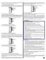
above lists the WattNode models and common circuit types. In the
“Electrical Service Types” column, when two voltages are listed with a slash
between them, they indicate the line-to-neutral / line-to-line voltages. The
“Line-to-Neutral” and “Line-to-Line” columns show the operating ranges for
the WattNode meters.
Ground
W
HI
TE
B
LAC
K
Ø
B CT
Ø
C CT
Ø
A CT
Ø
B
Ø
C
N
Ø
A
Common
B+, D1, RxD+/TxD+
EI
A-
48
5
Monitoring Device
A−, D0, RxD−/TxD−
Continental Control Systems LLC
Status
Status
Status
X
C
B+
A-
M
O
D
B
U
S
Com
WNC
-
WNC
-
W
ATT
N
ODE
®
M
ODBUS
-
MB
-
MB
Neutral
Phase A
Phase B
Phase C
LO
A
D
WHITE
BLACK
W
HI
TE
B
LAC
K
LI
N
E
Source
Faces
Current
Transformers
3Y
-
xxx
3D
-
xxx
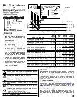
Figure 1: WattNode Wiring Diagram
Electrical
Service (or Load) Types
Line-to-
Neutral
(Vac)
Line-to-
Line
(Vac)
WattNode
Service
Type
Meter
Powered
by
1 Phase 2 Wire 120V with neutral
96 – 138
n.a.
3Y-208
N
and
Ø
A
1 Phase 2 Wire 230V with neutral (non-U.S.)
184 – 264
n.a.
3Y-400
N
and
Ø
A
1 Phase 2 Wire 277V with neutral
222 – 318
n.a.
3Y-480
N
and
Ø
A
1 Phase 2 Wire 208V no neutral
n.a.
166 – 276
3D-240
Ø
A
and
Ø
B
1 Phase 2 Wire 240V no neutral
n.a.
166 – 276
3D-240
Ø
A
and
Ø
B
1 Phase 3 Wire 120V/240V with neutral
96 – 138
166 – 276
3Y-208
N
and
Ø
A
3D-240
Ø
A
and
Ø
B
3 Phase 3 Wire Delta 208V no neutral
n.a.
166 – 276
3D-240
Ø
A
and
Ø
B
3 Phase 3 Wire Delta 400V no neutral (non-U.S.)
n.a.
320 – 460
3D-400
Ø
A
and
Ø
B
3 Phase 3 Wire Delta 480V no neutral
n.a.
384 – 552
3D-480
Ø
A
and
Ø
B
3 Phase 4 Wire Wye 120V/208V with neutral
96 – 138
166 – 276
3Y-208
N
and
Ø
A
3D-240
Ø
A
and
Ø
B
3 Phase 4 Wire Delta 120/208/240V with neutral
96 – 138
166 – 276
3D-240
Ø
A
and
Ø
B
3 Phase 4 Wire Wye 230V/400V with neutral
(non-U.S.)
184 – 264
320 – 460
3Y-400
N
and
Ø
A
3D-400
Ø
A
and
Ø
B
3 Phase 4 Wire Wye 277V/480V with neutral
222 – 318
384 – 552
3Y-480
N
and
Ø
A
3D-480
Ø
A
and
Ø
B
3 Phase 4 Wire Delta 240/415/480V with neutral
222 – 318
384 – 552
3D-480
Ø
A
and
Ø
B
3 Phase 4 Wire Wye 347V/600V with neutral
278 – 399
480 – 690
3Y-600
N
and
Ø
A
Table 1: WattNode Models
W
att
N
ode
®
M
odbus
and
W
att
N
ode
®
R
eveNue
Electric Power Meter
Installation Manual
Series - Service - Interface Options
______ - _______ - ________
3Y-208
3Y-400
3Y-480
3Y-600
3D-240
3D-400
3D-480
MB
= Modbus
®
See website
for options
WNC
= Third generation
RWNC
= Revenue, third generation
1 Precautions
1.1
Only qualified personnel or
licensed electri-
cians
should install the WattNode meter. The
mains voltages of 120 to 600 Vac can be lethal!
1.2
Follow all applicable local and national electri-
cal and safety codes.
1.3
The terminal block screws are
not
insulated.
Do not contact metal tools to the screw termi-
nals if the circuit is live!
1.4
Verify that circuit voltages and currents are
within the proper range for the meter model.
1.5
Use only UL listed or UL recognized current
transformers (CTs) with built-in burden resis-
tors, that generate 0.333 Vac (333 millivolts AC)
at rated current.
Do not use current output
(ratio) CTs such as 1 amp or 5 amp output
CTs: they will destroy the meter and may
create a shock hazard.
1.6
Protect the line voltage inputs to the meter with
fuses or circuit breakers (not needed for the
neutral or ground wires). See
below.
1.7
Equipment must be disconnected from the
HAZARDOUS LIVE voltages before access.
1.8
If the meter is not installed correctly, the safety
protections may be impaired.


