4
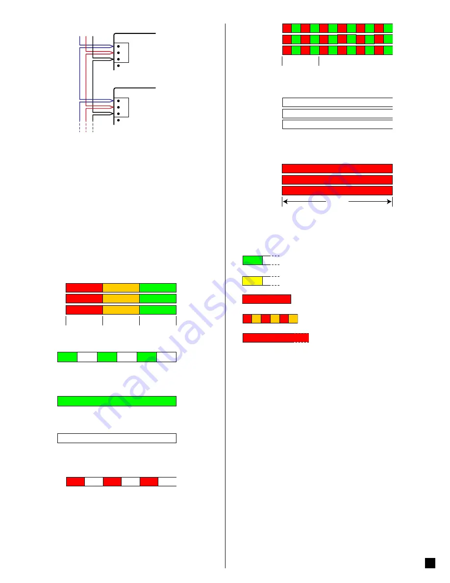
X
C
B+
A-
W
ATT
N
ODE
W
ATT
N
ODE
A- B+ C
RS-485
X
C
B+
A-
4 Operation
4.1 Initial Configuration
Generally, the network integrator will remotely configure the WattNode meter
and the variables. For details on configuring the WattNode meter, see the ap-
propriate
for your model.
The meter does not include a display or buttons, so it is not possible to configure
or monitor the meter directly, other than the basic LED diagnostics described
below.
At a minimum, the
CtAmps
must be programmed with the rated amps of the
attached current transformers for accurate measurements.
4.2 Power Status LEDs
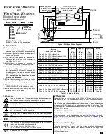
The three status LEDs on the front of the meter can help indicate correct opera-
tion. The “
A
”, “
B
”, and “
C
” on the diagrams indicate the three phases.
4.2.1 Normal Startup
The meter displays the following startup sequence whenever power is first
applied.
1.0sec
1.0sec
1.0sec
Green
Yellow
Red
Green
Yellow
Red
Green
Yellow
Red
C
B
A
4.2.2 Positive Power
Any phase with the LEDs flashing green is indicating normal positive power.
Green
Off
Green
Off
Green
Off
4.2.3 No Power
Any phase with a solid green LED indicates no power, but line voltage is pres-
ent.
Green
4.2.4 No Voltage
Any phase LED that is off indicates no voltage on that phase.
Off
4.2.5 Negative Power
Red flashing indicates negative power for that phase. Reversed CTs, swapped
CT wires, or CTs not matched with line voltage phases can cause this.
Red
Off
Red
Off
Red
Off
C
4.2.6 Overvoltage Warning
The following indicates that the line voltage is too high for this model.
Discon-
nect power immediately!
Check the line voltages and the meter ratings (in
the white box on the label).
1.0sec
G
R
G
R
G
R
G
R
G
R
G
R
G
R
G
R
G
R
G
R
G
R
G
R
G
R
G
R
G
R
G
R
G
R
G
R
C
B
A
4.2.7 Meter Not Operating
If none of the LEDs light, then check that the correct line voltages are applied
to the meter. If the voltages are correct, call customer service for assistance.
Off
Off
Off
C
B
A
4.2.8 WattNode Error
If the meter experiences an internal error, it will light all LEDs red for three or
more seconds. If you see this happen repeatedly, return the meter for service.
3.0sec
Red
Red
Red
C
B
A
For other LED patterns, see the
or contact
support for assistance.
4.3 Modbus Communication LED
Near the upper left corner, there is a diagnostic
Com
(communication) LED
that can indicate the following:
●
Green Off
A short green flash indicates a valid packet addressed to
this device.
●
Yellow Off
Short yellow flashes or rapid flashing indicate valid packets
addressed to different devices.
●
Red
A one second red flash indicates an invalid packet: bad
baud rate, bad CRC, noise, bad parity, etc.
●
Y
R
Y
R
Y
R
Rapid red/yellow flashing indicates a possible ad-
dress conflict (two devices with the same DIP switch address).
●
Red
Solid red indicates the address is set to zero:
an invalid choice.
4.4 Monitoring
The meter does not include a display or buttons, so it is not possible to oper-
ate the meter directly. The following is a brief overview of the possible remote
monitoring.
The WattNode Modbus meter models communicate measurements over a
Modbus RTU network. The measurements include: energy, power, voltage,
current, line frequency, power factor, reactive power, and demand.
In order to monitor and configure networked WattNode models, you will need
an appropriate monitoring solution, either standalone or PC software.
See the
for a complete list of network ac-
cessible variables.
4.5 Maintenance and Repair
The WattNode meter requires no maintenance. It is not user serviceable and
there are no replaceable parts except the pluggable screw terminals. There are
no diagnostic tests that can be performed by the user, other than checking for
errors via the communications interface or the status LEDs.
In the event of any failure, the meter must be returned for service (contact CCS
for an RMA). For a new installation, follow the diagnostic and troubleshooting
instructions in the
before returning the meter
for service, to ensure that the problem is not connection related.
The WattNode meter should not normally need to be cleaned, but if cleaning
is desired, power must be disconnected first and a dry or damp cloth or brush
should be used.


