


14
ISOMIX HC-IM-DE-W-DE-10-2018-Rev1_enUS | Art. No. 10070436
EN
ENGLISH
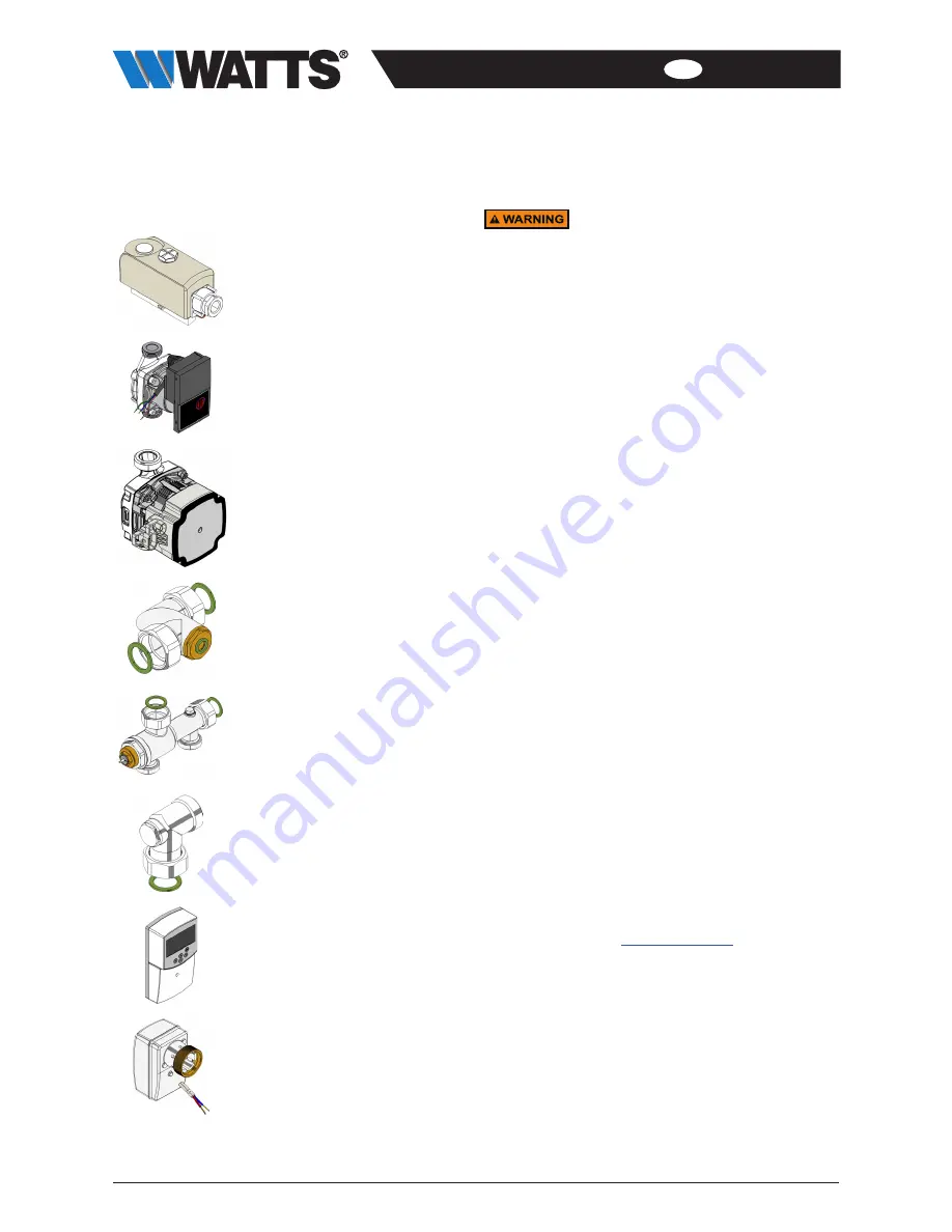
10 Spare parts list
Spare part
Art. no.:
WTC-IS
temperature limiter
internal setting
10013410
Yonos PARA 15/6 pump
1” male thread, L = 130mm
Wilo
10080331
UPM3 Auto L15-70 pump
1” male thread, L = 130mm
Grundfos
10080353
Isomix-HC eccentric
1” fl. x 1” fl.
10080536
Isomix-F / HC thermal
mixer valve
2x1” male thread x 2x1” fl.
10080537
Isomix-HC bracket
1” male thread x 1”fl.
10080540
Climatic control regulator
CC-HC
10021172
Actuator
3-point 230 V
10027254
11 Disposal
Potential for contamination of the
environment and groundwater from
improper disposal!
The legal regulations and guidelines
in the country of operation must be
observed when disposing of components
and operating materials.
1. Ensure that all assemblies and components are
de-energized.
2. Disassemble the Isomix properly or commission a
specialist company to do so.
3. Sort the assemblies and component parts into recyclable
materials, hazardous substances and operating materials.
4. Dispose of the assemblies and components in
accordance with local laws and regulations or take them
to be recycled.
11.1 Return to the manufacturer
Get in contact with the manufacturer if you would like to
return the Isomix or parts of it.
11.2 Notification of administrative bodies and
the manufacturer
Inform the manufacturer of decommissioning and disposal of
the Isomix for statistical purposes.
12 Warranty
WATTS products are tested extensively. WATTS therefore
guarantees only to replace or repair components of the
products supplied free of charge – at the sole discretion of
WATTS – if, in the opinion of WATTS, they exhibit verifiable
manufacturing faults. Warranty claims due to defects
or defects of title may be asserted within one (1) year of
delivery/transfer of risk. Excluded from the warranty is
damage attributable to normal product use or friction and
to damage resulting from modifications or unauthorized
repairs to the products, for which WATTS rejects all claims
for compensation (direct or indirect). (For more detailed
information, please refer to our website.) In all cases, supply
is subject to the General Terms and Conditions,
which can be found on
www.wattswater.de
.


