background image

ISOMIX HC-IM-DE-W-DE-10-2018-Rev1_enUS | Art. No. 10070436

9

EN

ENGLISH

6.2  Initial commissioning

All screw fittings must be checked and tightened if 
necessary prior to installation and commissioning!

Torque:

•  ¾” screw fittings 35 Nm
•  1” screw fittings 55 Nm
•  1

1/2

” screw fittings 130 Nm

1.  Connect the control station to the pipe network.
2.  Shut off the ball valves (using ball valves (15) supplied 

with the heating circuit manifold or shut-off device fitted 
by the customer). 

3.  Switch off the pump and close all of the heating circuits 

on the distributor. 

It is sufficient to close the valves in the return 
collector of the heating circuit manifold with the 
protection caps.

4.  Fill the manifold and control station with hot water (in 

accordance with VDI 2035): 

5.  connect the filling hose to the fill and drain valve on the 

return (5-9b) and the draining hose to the fill and drain 
valve on the supply (5-9a). 

Heating circuits are closed. 

6.  Open both fill and drain valves and fill the manifold and 

control station until water comes out of the fill and drain 
valve on the supply. 

7.  Close both fill and drain valves.
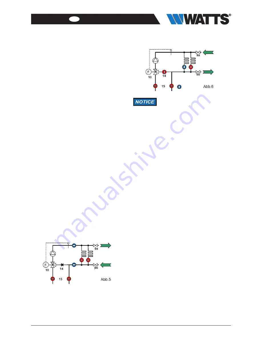
8.  To fill and flush the heating circuits, connect the filling 

hose to the supply fill and drain valve (6-9a) and the 
emptying hose to the return fill and drain valve (6-9b). 

9.  Open the heating circuit to be flushed. 
10. Open fill and drain valve and flush out the heating circuit 

in the direction of flow until the air and any contamination 
has been removed from the circuit completely. 

The non-return valve (14) in the mixer bypass prevents 
any short circuit when flushing.

11. Repeat the process for all the heating circuits.

Flushing is permitted only in the direction 
of flow of the heating circuits, i.e. the 
water must enter through the flow 
manifold and come out of the return! 
The drain must always be open, as 
otherwise the high water pressure could 
damage the heating system.  
The instructions on flushing in the 
operating manual for the heating circuit 
manifold must also be observed.

Summary of Contents for Isomix-HC

Page 1: ...n surface heating cooling systems Installation and Operating Manual translated from the original operating manual Issued 10 2018 Revision 1 Watts Industries Deutschland GmbH Godramsteiner Hauptstr 167 76829 Landau Germany Tel 49 0 6341 96560 wide wattswater com WattsWater de ...

Page 2: ...on about the installa tion and operating manual The plant operator is responsible for ensuring compliance with the local laws and regulations e g accident prevention regulations etc Incorrect operation or operating the Isomix outside the specifications invalidates all warranty claims This installation and operating manual is an integral part of the Isomix contains instructions and information abou...

Page 3: ...ol mixture as per VDI 2035 ÖNORM Austrian standard 5195 Weight Total weight net approx 4 72 kg Total weight gross approx 5 05 kg Connections to pipe network 1 male thread primary heat generator 1 fl secondary heat distribution Isomix 1 flat sealing Materials Fittings Brass CW617 N nickel plated Seals and O rings AFM34 2 and EPDM Plastics Impact resistant and temperature resistant Circulation pump ...

Page 4: ...grated HEATING COOLING controller in accordance with the external temperature by means of a selectable heating cooling curve The steepness of the curve can be selected in accordance with the conditions at the location further details can be found in the operating manual for the controller The Isomix HC can be used to operate a heating system that is set to the individual requirements of a home or ...

Page 5: ...ve read these operating instructions and understood the potential hazards associated with improper behavior Fitters commissioning engineers Fitters commissioning engineers are in a position to carry out work on the Isomix taking into consideration the applicable standards provisions regulations and laws and their technical training and technical knowledge and can detect and prevent potential hazar...

Page 6: ...g controller There is a non return valve between the primary feed and the return connection on the mixer valve which prevents a short circuit in the primary circuit 6 Installation and commissioning Electrical energy Risk of death from electric shock Work on parts carrying live voltage must be carried out by qualified electricians only Disconnect the power supply of the system and secure it to prev...

Page 7: ...rive Red Blue White CLOSE OPEN System diagram of heating elements and surface heating cooling system Separate heating and cooling generator Separate risers System diagram of heating elements and surface heating system One heat generator Shared riser System diagram of surface heating cooling system Separate heating and cooling generator System diagram of surface heating cooling system Reversible he...

Page 8: ...xer tap More detailed information on scalding protection can be found in DIN 1988 sheet 2 section 4 2 During installation it must be ensured that the cables from the pump and temperature limiter are not kinked The cables must not be under tension 1 Fit the control station to the manifold with the 1 nuts and associated seals The control station can be fitted on the right or left of the manifold by ...

Page 9: ...a Heating circuits are closed 6 Open both fill and drain valves and fill the manifold and control station until water comes out of the fill and drain valve on the supply 7 Close both fill and drain valves 8 To fill and flush the heating circuits connect the filling hose to the supply fill and drain valve 6 9a and the emptying hose to the return fill and drain valve 6 9b 9 Open the heating circuit ...

Page 10: ... Use in combination with Watts Heat Interface Unit HIU 2 For use in combination with the HIU 2 Heat Interface Unit the Isomix HC must be converted overhead and the eccentric rotated 1 Release nut A A 2 Rotate eccentric B C B B Eccentric C Position of the contact thermostat ...

Page 11: ...ISOMIX HC IM DE W DE 10 2018 Rev1_enUS Art No 10070436 11 EN ENGLISH 7 Pressure loss curve Pressure loss Isomix floor control unit Pressure loss mbar Flow rate L h ...

Page 12: ...d 2 Functional check Check that settings and operating and performance parameters are set correctly Check flow noise during operation Ask users if there are any noticeable problems 3 Action to be taken following maintenance work Check that all screw fittings that were unscrewed have been retightened and retighten if necessary Remove all tools materials and other equipment used from the working are...

Page 13: ...ore causes the 3 way mixer valve to open Hot water is injected from the primary heating circuit As a result the control station heats up When the maximum temperature of the TL is reached the contact opens The pump does not switch on again Remove TL from the control station and fit to supply heating circuit manifold See 1 1 2 Underfloor heating flow temperature cannot be set to the required value o...

Page 14: ... materials 4 Dispose of the assemblies and components in accordance with local laws and regulations or take them to be recycled 11 1Return to the manufacturer Get in contact with the manufacturer if you would like to return the Isomix or parts of it 11 2 Notification of administrative bodies and the manufacturer Inform the manufacturer of decommissioning and disposal of the Isomix for statistical ...

Reviews: