AERCO ProtoNode FPC-N34 & FPC-N35 User Manual
CHAPTER 3 – Interfacing ProtoNode to Devices
OMM-0107_0B
AERCO International, Inc.
•
100 Oritani Dr.
•
Blauvelt, NY 10913
Page
25
of
108
GF-150
Ph.: 800-526-0288
03/07/2017
3.6 Power-Up ProtoNode
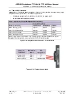
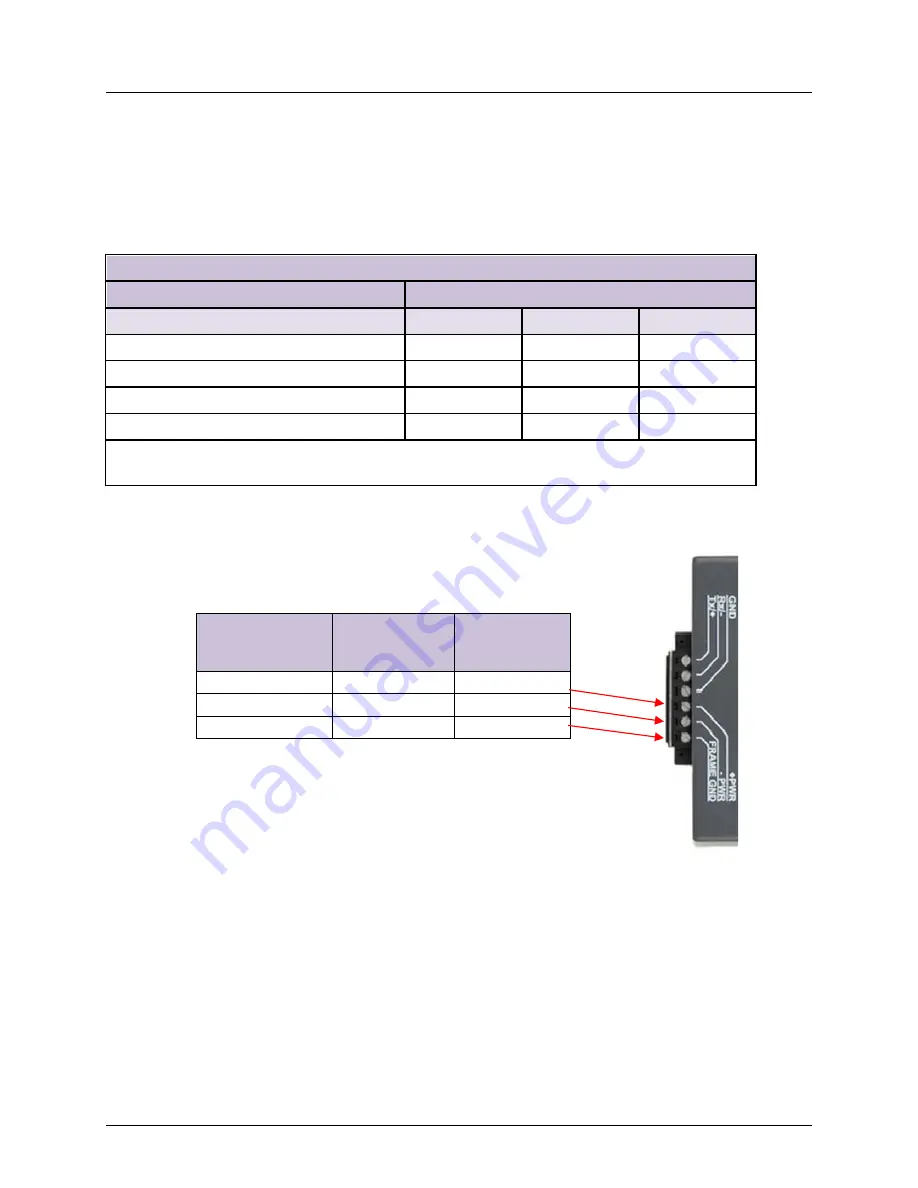
Apply power to ProtoNode as shown below in Figure 3-15 Ensure that the power supply used
complies with the specifications provided in Appendix J-1
.
•
ProtoNode accepts either 9-30VDC or 12-24 VAC on pins 4 and 5.
•
Frame GND should be connected.
Power Requirement for ProtoNode External Gateway
Current Draw Type
ProtoNode Family
12VDC/VAC
24VDC/VAC
30VDC
FPC – N34 (Typical)
170mA
100mA
80mA
FPC – N34 (Maximum)
240mA
140mA
100mA
FPC – N35 (Typical)
210mA
130mA
90mA
FPC – N35 (Maximum)
250mA
170mA
110mA
Note: These values are ‘nominal’ and a safety margin should be added to the power
supply of the host system. A safety margin of 25% is recommended.
Figure 3-14: Required current draw for the ProtoNode
Figure 3-15: Power Connections
Power to
ProtoNode
ProtoNode
Pin #
Pin
Assignment
Power In (+)
Pin 4
V +
Power In (-)
Pin 5
V -
Frame Ground
Pin 6
FRAME GND


