AERCO ProtoNode FPC-N34 & FPC-N35 User Manual
CHAPTER 3 – Interfacing ProtoNode to Devices
Page
18
of
108
AERCO International, Inc.
•
100 Oritani Dr.
•
Blauvelt, NY 10913
OMM-0107_0B
03/07/2017
Ph.: 800-526-0288
GF-150
3.2 Device Connections to ProtoNode
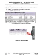
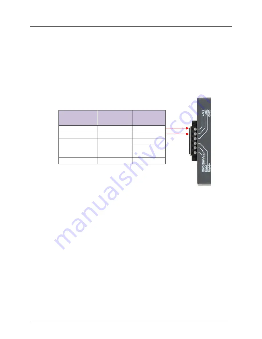
ProtoNode 6 Pin Phoenix connector for RS-485 Devices
•
The 6 pin Phoenix connector is the same for ProtoNode FPC-N34 and FPC-N35
.
•
Pins 1 through 3 are for Modbus RS-485 devices.
o
The RS-485 GND (Pin 3) is not typically connected.
•
Pins 4 through 6 are for power.
Do not connect power
(wait until Section 3.6).
Figure 3-2: Power and RS-485 Connections
Device Pins
ProtoNode
Pin #
Pin
Assignment
Pin RS-485 +
Pin 1
RS-485 +
Pin RS-485 -
Pin 2
RS-485 -
Pin GND
Pin 3
RS-485 GND
Power In (+)
Pin 4
V +
Power In (-)
Pin 5
V -
Frame Ground
Pin 6
FRAME GND


