background image

AM Series Pool Heater User Manual


SECTION 7: INSTALLATION 

– ELECTRICAL 


OMM-0111_B:  

  GF-146-P 

  10/29/2019             

Technical Support


  (800) 526-0288  

  Mon-Fri, 8 am - 5 pm EST           Page 37  of 47 


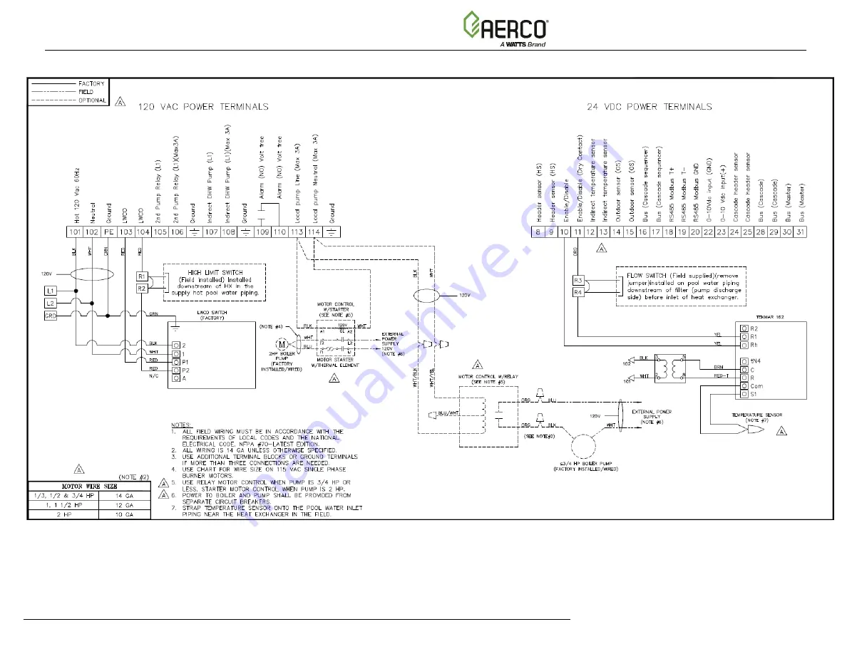
Figure 7-2: Pool Heater Boiler Electrical Connections

Summary of Contents for Aerco AM Series

Page 1: ...subject to change without notice from AERCO International Inc AERCO makes no warranty of any kind with respect to this material including but not limited to implied warranties of merchantability and...

Page 2: ...CES TO COMBUSTIBLE MATERIAL 19 3 7 TRANSPORTING THE AM SERIES POOL HEATER 19 SECTION 4 INSTALLATION VENT AND AIR 22 4 1 VENT AND COMBUSTION AIR PIPING 22 4 2 PREVENTION OF COMBUSTION AIR CONTAMINATION...

Page 3: ...s 38 7 1 4 MODBUS Interface Connections Boilers and Water Heaters 38 7 2 ELECTRICAL CONNECTIONS BOILERS ONLY 39 7 2 1 Pool Flow Switch Connections 39 7 2 2 Pool Water High Limit Switch Connections 40...

Page 4: ...wn 8 1 to 20 1 depending on unit Low NOx Emission 20ppm Direct or Conventional Vent with PVC CPVC Polypropylene or AL29 4C materials Concentric Vent Capability Common Vent Capability Side wall common...

Page 5: ...Failure to comply with provisions warnings and cautions provided in this manual can lead to extensive property damage and or personal injury or death In the event of a breakdown and or malfunction of...

Page 6: ...ng compounds in the boiler system Gaskets and seals in the system may be damaged This can result in substantial property damage The manufacturer declines all liability contractual or otherwise warrant...

Page 7: ...AM Series Pool Heater User Manual CHAPTER 1 GENERAL INFORMATION OMM 0111_B GF 146 P 10 29 2019 Technical Support 800 526 0288 Mon Fri 8 am 5 pm EST Page 7 of 47 OFF OFF...

Page 8: ...rsonnel Figure 1 1 Manual Gas Shutoff Valve IMPORTANT FOR MASSACHUSETTS INSTALLATIONS Boiler Installations within the Commonwealth of Massachusetts must conform to the following requirements Boiler mu...

Page 9: ...er Manual GF 146 Figure 2 1 shows the exterior appearance of an AM Series Pool heating system as it comes factory configured and installed on a skid The AM Series Pool Heater comes in four functionall...

Page 10: ...excess oxygen A modulating gas valve and variable speed fan meter the natural gas and air input respectively Each module has a dedicated isolation valve on the inlet side of the module on the rear of...

Page 11: ...11_B GF 146 P 10 29 2019 Technical Support 800 526 0288 Mon Fri 8 am 5 pm EST Page 11 of 47 Figure 2 3a AM 399P 500P Pool Heater Connection Dimensions NOTE These drawings and or dimensions are subject...

Page 12: ...11_B GF 146 P 10 29 2019 Technical Support 800 526 0288 Mon Fri 8 am 5 pm EST Page 12 of 47 Figure 2 3b AM 750P 1000P Pool Heater Connection Dimensions NOTE These drawings and or dimensions are subjec...

Page 13: ...erates with an Inverse Efficiency Curve with known Part Load Value Efficiencies There are five 5 modes in which the AM boiler may be set each one adjusting this performance according to specific requi...

Page 14: ...e with BACnet Lonworks and N2 shall utilize an optional AERCO Communications Gateway to act as a MODBUS interface translator between the BAS the communications The AERCO Communications Gateway is comp...

Page 15: ...AM Series Pool Heater User Manual CHAPTER 2 FUNCTION SPECIFICATIONS OMM 0111_B GF 146 P 10 29 2019 Technical Support 800 526 0288 Mon Fri 8 am 5 pm EST Page 15 of 47 This Page Is Intentionally Blank...

Page 16: ...for removal of unburned gas This appliance is not designed for direct outdoor installation If installed outside of the structure it must be sheltered so it is protected from rain wind sun and frost NE...

Page 17: ...mmable materials or liquids in the immediate vicinity of the boiler 3 4 Closet and Alcove Installation This heater is approved for the installation in an alcove or closet within compliance of the guid...

Page 18: ...8 Mon Fri 8 am 5 pm EST Page 18 of 47 Figure 3 1a Recommended Minimum Service Clearances AM 399 AM 500 Figure 3 1b Recommended Minimum Service Clearances AM 750 AM 1000 32 20 REAR FRONT Or per piping...

Page 19: ...urer s instructions The vent system must conform to all manufacturer s recommendations and shall utilize UL listed stainless steel AL 29 4C Polypropylene PVC or CPVC Positive Pressure venting material...

Page 20: ...sing a fork lift inserted into the skid at front green arrows or at the sides yellow arrows as indicated by in Figure 3 2 Figure 3 2 Transporting the AM Series Pool Heater CAUTION DO NOT use the lifti...

Page 21: ...AM Series Pool Heater User Manual SECTION 3 INSTALLATION SITE OMM 0111_B GF 146 P 10 29 2019 Technical Support 800 526 0288 Mon Fri 8 am 5 pm EST Page 21 of 47 This Page Is Intentionally Blank...

Page 22: ...for installation using room combustion air When room combustion air is considered see Chapter 6 Vent and air may be vented vertically through the roof or out a side wall unless otherwise speci ed You...

Page 23: ...AM Series Pool Heater User Manual SECTION 4 INSTALLATION VENT AND AIR OMM 0111_B GF 146 P 10 29 2019 Technical Support 800 526 0288 Mon Fri 8 am 5 pm EST Page 23 of 47 This Page Is Intentionally Blank...

Page 24: ...must be less than 200 ppm total dissolved solids TDS Artificial Softness Do NOT use artificially softened water Artificial softening agents generally use salt which creates a chloride water chemistry...

Page 25: ...s toxic and can corrode gaskets and seals WARNING Never use non approved additives or toxic boiler treatment chemicals in the heating system Any additives introduced into the heating system must be re...

Page 26: ...in to prevent injury in the event of pressure relief Each relief valve must have its own discharge piping be piped to within 12 of the ground and not be combined with any other piping all the way to t...

Page 27: ...hrough pipe C Figure 4 8 and E Figure 4 9 and empties into the floor drain or drain pan F Figure 5 3 NOTE In newer units hose A Fig 5 2 attaches to a port at the bottom of flue rather than the side Th...

Page 28: ...vice and maintenance 5 8 Pool Water Connections to the Heat Exchanger The supply and return water piping connection size to the indirect heat exchanger is 1 1 2 NPT for models AM 399P 500P and 2 NPT f...

Page 29: ...Piping Method A full flow system is recommended if the total system flow of the swimming pool or spa system is within five gallons per minute of the recommended system water flow as shown in the tabl...

Page 30: ...nger If pool or spa water system exceeds 95 F in temperature a bypass flow configuration is used to cool down the return flow in order to prevent tripping the high limit switch and to prevent water wi...

Page 31: ...AM Series Pool Heater User Manual SECTION 5 INSTALLATION PIPING OMM 0111_B GF 146 P 10 29 2019 Technical Support 800 526 0288 Mon Fri 8 am 5 pm EST Page 31 of 47...

Page 32: ...regulators are recommended on every unit but not required NOTE For installation in Massachusetts an individual gas regulator is required on every unit regardless of incoming gas pressure 6 2 Natural G...

Page 33: ...tion check the appliance and its gas connection for leaks a The appliance must be disconnected from the gas supply piping system during any pressure testing of that system at a test pressure in excess...

Page 34: ...400 600 1160 1840 3260 6640 70 N A 179 368 552 1060 1690 3000 6110 80 N A 167 343 514 989 1580 2790 5680 90 N A 157 322 482 928 1480 2610 5330 100 N A 148 304 455 877 1400 2470 5040 125 N A 131 269 4...

Page 35: ...com for further information For installations at higher altitudes in the United States follow local codes or in the absence of local codes follow ANSI Z223 1 NFPA No 54 The National Fuel Gas Code and...

Page 36: ...pm EST Page 36 of 47 SECTION 7 INSTALLATION ELECTRICAL 7 1 Electrical Connections Boiler 7 1 1 Power Supply Cable Connection Provide and install a fused disconnect or service switch 15 amp recommended...

Page 37: ...Pool Heater User Manual SECTION 7 INSTALLATION ELECTRICAL OMM 0111_B GF 146 P 10 29 2019 Technical Support 800 526 0288 Mon Fri 8 am 5 pm EST Page 37 of 47 Figure 7 2 Pool Heater Boiler Electrical Co...

Page 38: ...ere If the input voltage stays below 1 5V the heater stays OFF If the input voltage increases to between 1 5V and 2 0V the heater start to operate and the supply temperature stays at the value set for...

Page 39: ...manual GF 146 2 Connect the leads of a two conductor cable with a minimum cross section of 18 AWG to your enable disable controller and run the cable to the boiler electrical junction box NOTE AERCO...

Page 40: ...res and follow installation instructions that comes with the high limit switch 3 Open the boiler electrical junction box cover and connect the leads of the cable to terminals R1 and R2 see Figure 7 2...

Page 41: ...ECTION 11 BOILER TECHNICAL DATA REFERENCE NOTE For all information regarding the technical data of the boiler refer to Section 12 of the AM Series User Manual GF 146 SECTION 12 BOILER PARTS DRAWINGS L...

Page 42: ...ystem Parts Drawing and List Equipment List Models AM399P 016 AM500P 016 Item Part Description 1 Base 2 AM399B AM500B Boiler 3 0066605 Expansion Tank 4 99124 Pump 5 63063 Relay 6 N A Starter 7 1605026...

Page 43: ...st Models AM399P 075 AM500P 075 Item Part Description 1 Base 2 AM399B AM500B Boiler 3 0066605 Expansion Tank 4 99126 Pump 5 63190 Relay 6 N A Starter 7 16050265 001 Pool Heat Exchanger 8 92081 2 5 Cir...

Page 44: ...and List Equipment List Models AM750P 016 AM1000P 016 Item Part Description 1 Base 2 AM750B AM1000B Boiler 3 0066605 Expansion Tank 4 99124 Pump 5 63063 Relay 6 N A Starter 7 28567 Pool Heat Exchange...

Page 45: ...ipment List Models AM750P 200 AM1000P 200 Item Part Description 1 Base 2 AM750B AM1000B Boiler 3 0066605 Expansion Tank 4 69231 Pump 5 N A Relay 6 63191 Starter 7 28567 Pool Heat Exchanger 8 92081 2 5...

Page 46: ...s or workmanship All other boiler components carry an 18 month warranty against failure due to defective materials or workmanship If any part of skid package fails because of a manufacturing defect wi...

Page 47: ...019 Technical Support 800 526 0288 Mon Fri 8 am 5 pm EST Page 47 of 47 Change Log DATE DESCRIPTION CHANGED BY 11 29 2018 Rev A Initial release 10 29 2019 Rev B Parts List Update Section 13 2 Wiring Up...

Reviews: