Benchmark 750-3000 Installation & Startup Manual
SECTION 2
– INSTALLATION
OMM-115_D
•
GF-200
•
5/9/2019
Technical Support
•
(800) 526-0288
•
Mon-Fri, 8 am - 5 pm EST Page 30 of
126
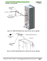
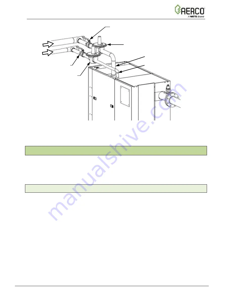
Figure 2-7c: BMK 1500-3000DF Dual Fuel Manual Gas Shut-Off Valve & Gas
Regulator
2.10 AC ELECTRICAL POWER WIRING
For electrical power requirements and wiring diagrams for all Benchmark models 750
– 3000,
both domestic and international, see the AERCO
’s
Benchmark Electrical Power Guide
, TAG-
0048 (GF-2060). This guide must be consulted prior to connecting any AC power wiring to the
unit.
2.10.1 Electrical Power Requirements
Each unit must be connected to a dedicated electrical circuit.
NO OTHER DEVICES SHOULD
BE ON THE SAME ELECTRICAL CIRCUIT AS THE BOILER.
A switch must be installed on the electrical supply line in an easily accessible location to quickly
and safely disconnect electrical service. DO NOT attach the switch to sheet metal enclosures of
the unit.
After placing the unit in service, the ignition safety shutoff device must be tested. If an external
electrical power source is used, the installed boiler must be electrically bonded to ground in
accordance with the requirements of the authority having jurisdiction. In the absence of such
requirements, the installation shall conform to National Electrical Code (NEC), ANSI/NFPA 70
and/or the Canadian Electrical Code (CEC) Part I, CSA C22.1 Electrical Code.
NATURAL GAS INLET
NATURAL GAS PRESSURE REGULATOR
PROPANE MANUAL SHUT-
OFF VALVE
NATURAL GAS
SUPPLY
PROPANE
SUPPLY
PROPANE PRESSURE
REGULATOR
NATURAL GAS MANUAL
SHUT-OFF VALVE
PROPANE INLET
NOTE
In propane-only units, the
natural gas piping and
components
shown
in
Figure 2-7c will not be
present.

