Benchmark 750-3000 Installation & Startup Manual
SECTION 2
– INSTALLATION
OMM-115_D
•
GF-200
•
5/9/2019
Technical Support
•
(800) 526-0288
•
Mon-Fri, 8 am - 5 pm EST Page 21 of
126
2.6 SUPPLY AND RETURN PIPING
2.6.1 BMK 750
–
1000 Supply and Return Piping
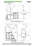
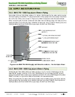
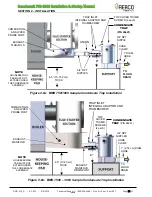
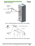
Benchmark 750 and 1000 Boiler utilizes 3” (7.62cm) 150# flanges for the water system supply
and return piping connections. The physical location of the supply and return piping connections
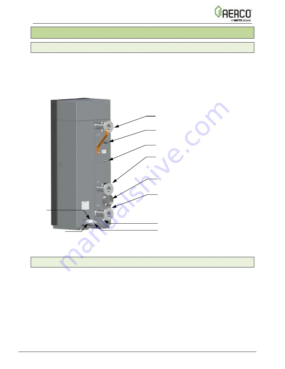
are on the rear of the unit as shown in Figure 2-4a. Refer to Appendix A for dimensional data.
When connecting the hot water outlet and cold water inlet to building piping, first make sure the
mating surfaces are thoroughly clean. AERCO recommends using Loctite ® 7649 to prime the
mating surfaces and then Loctite 567 as pipe dope. Do
NOT
use Teflon tape.
Figure 2-4a: BMK 750/1000 Supply and Return Locations
–
Two Inlet Option Shown
2.6.2 BMK 1500
–
3000 Supply and Return Piping
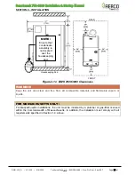
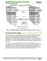
All Benchmark 1500, 2000, 2500 and 3000 units
have one 4” (10.2 cm) 150# flanges for the
water INLET (supply) and one 4” (10.2 cm) 150# flanges for the hot water OUTLET (return)
piping connections. Some units have an optional second 4” (10.2 cm) 150# flange for the water
INLET, as shown in Figure 2-4b. Refer to Appendix A for dimensional data.
When connecting the hot water outlet and cold water inlet to building piping, first make sure the
mating surfaces are thoroughly clean. AERCO recommends using Loctite ® 7649 to prime the
mating surfaces and then Loctite 567 as pipe dope. Do
NOT
use Teflon tape.
1” (2.54cm) NATURAL GAS INLET
1/4” ANALYZER
NPT PORT
3” HOT WATER OUTLET
(SUPPLY)
CONDENSATE DRAIN
AIR INLET
3”
PRIMARY
WATER INLET
COOLER
WATER RETURN
DRAIN VALVE
3”
SECONDARY
WATER INLET
WARMER
WATER RETURN
EXHAUST
MANIFOLD
1” (2.54cm) PROPANE INLET

