Benchmark 5000-6000 Operation & Maintenance Manual
SECTION 2: OPERATION
OMM-0118_B
•
GF-203
•
5/9/2019
Technical Support
•
(800) 526-0288
•
Mon-Fri, 8 am - 5 pm EST Page 27 of 148
*
NOTE
:
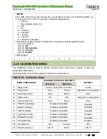
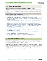
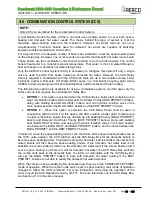
The 1 BST Units 8 menu item shows the current status for each unit controlled by BST, up
to a maximum of 8 units. The possible characters displayed are:
- = Off Line
* = Not Available (fault, etc.)
0 = Off
1 = On,
A = Lead On
a = Lead Off
B = Lag On
b = Lag Off
S = Setpoint Limit Active
The following example shows the status of 5 units being controlled by BST where:
Unit 1 & 3 are
On
Unit 2 is
Off
Unit 4 is
Not Available
Unit 5 is
Lead On
Unit 6 is
Lag Off
1 BST Units 8
1
0
1
*
A
b
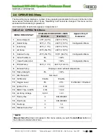
2.10 CALIBRATION MENU
The Calibration menu is used by factory trained service personnel to adjust or reset the
parameters listed below.
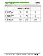
A full description of each item appears in Table A-6 of Appendix A.
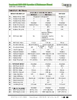
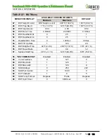
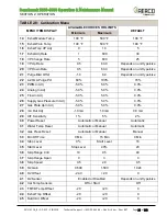
TABLE 2-8: Calibration Menu
MENU ITEM DISPLAY
AVAILABLE CHOICES OR LIMITS
DEFAULT
Minimum
Maximum
1
Stepper Fbk
Cal 0%, Verify 50%, Cal 100%
Cal 0%
2
Purge Timer
5 sec.
60 sec
Depends on unit type/size
3
Post Purge Timer
0 sec.
60 sec.
0 sec.
4
IGN Position
5%
60%
Depends on unit type/size
5
Ign Pos Hold Tmr
0 sec.
60 sec.
0 sec.
6
FFWD Temp Disply
Enabled or Disabled
Disabled
7
Outlet Tmp Dsply
Enabled or Disabled
Disabled
8
Inlet Tmp Dsply
Enabled or Disabled
Disabled
9
Valv Pos Out Dsp
Enabled or Disabled
Enabled
10
Exhaust Tmp Dsp
Enabled or Disabled
Disabled
11
Exhaust Safety
Enabled or Disabled
Enabled
12
Flue Material
PVC
Stainless
PVC
13
Exhst Fault Temp
100 °F
500 °F
200 °F


