Benchmark 5000-6000 Operation & Maintenance Manual
SECTION 4
– MAINTENANCE
OMM-0118_B
•
GF-203
•
5/9/2019
Technical Support
•
(800) 526-0288
•
Mon-Fri, 8 am - 5 pm EST Page 44 of 148
4.5 COMBUSTION CALIBRATION & PILOT REGULATOR
ADJUSTMENT
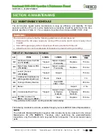
Combustion settings must be checked at the intervals shown in Table 4-1 as part of the
maintenance requirements. Refer to Section 4.5 of the
Benchmark 5000
– 6000 Installation and
Startup Guide, OMM-0117 (GF-202)
for combustion calibration instructions. Pilot Regulator tests
and adjustments are performed using the procedures in Section 4.5.1 and Section 4.5.2, below.
4.5.1 Pilot Regulator Pressure Testing
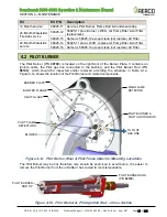
Benchmark 5000 & 6000 standard models feature one Pilot Regulator system in the Natural
Gas gas train, while Benchmark 5000 & 6000 Dual Fuel units have two Pilot Regulator
systems, one in the Natural Gas gas train (see Figure 4-4a) and one in the Propane gas train
(see Figure 4-4b).
Both Pilot Regulators should be pressure tested annually as described below. If the gas
pressure is
below
4.6” W.C. (1.1 kPa)
or
above
5.0” W.C. (1.2 kPa)
in either regulator, then
that regulator must be recalibrated using the instructions in Section 4.5.2.
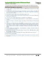
The following pressure test is performed on both the Natural Gas and Propane Pilot Regulators:
Pilot Regulator Pressure Test Procedure Instructions
1. Ensure that gas supply shut-off valve upstream of the unit is still turned
OFF
.
2. Turn OFF electrical power to the system.
3.
Remove the 1/4” NPT plug from the Tee on the outlet side of the Pilot Regulator (Figure 4-
4a or Figure 4-4b) and insert a NPT-to-barbed adapter fitting.
4.
Attach one end of the plastic tubing to the barbed fitting and the other end to the 16” W.C.
(4.0 kPa) manometer.
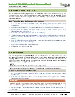
5. Remove the cap from the Pilot Regulator to access the gas pressure adjustment. Rotate
the regulator adjustment (beneath cap) clockwise (CW) to its highest possible pressure
setting.
6. Next, rotate the adjustment screw 2 turns counterclockwise (CCW).
7. OPEN the main gas supply upstream of the unit.
8. Turn ON electrical power to the system.
9. Start the boiler in MANUAL mode. Observe the manometer pressure when the Pilot
solenoid “clicks” open after purge. It should now provide a reading of
4.8 ± 0.2” W.C. (1.2
kPa ± 50 Pa)
.
10. Pull out one of the Pilot Flame Detectors (see Figure 4-1a, above) and look into the
observation port on the front plate. You should see the orange glow of the Pilot flame
during the ignition trial period.
11. If the pressure is within specifications, remove the manometer and replace the cap on the
Pilot Regulator, then return the unit to service. Make sure that the unit is operating in
AUTO mode. The “MAN” light in the upper left of the C-More Controller should NOT be lit
when in AUTO mode.
12. If the Pilot Regulator is NOT within specifications, proceed to Section 4.5.2 and perform the
Pilot Regulator Pressure Calibration procedure.


