Benchmark 5000-6000 Operation & Maintenance Manual
SECTION 4
– MAINTENANCE
OMM-0118_B
•
GF-203
•
5/9/2019
Technical Support
•
(800) 526-0288
•
Mon-Fri, 8 am - 5 pm EST Page 46 of 148
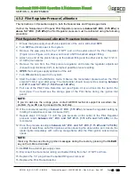
4.5.2 Pilot Regulator Pressure Calibration
The instructions in this section apply to both the Natural Gas and Propane gas trains.
If either the Natural Gas or Propane Pilot Regulator pressure is
below 4.6
” W.C. (1.15 kPa)
or
above
5.0” W.C.
(1.25 kPa)
the Pilot Regulator pressure must be calibrated using the following
procedure:
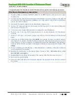
Pilot Regulator Pressure Calibration Procedure Instructions
1. Ensure that gas supply shut-off valve upstream of the unit is still turned
OFF
.
2. Turn
OFF
electrical power to the system.
3. Remove the pipe plug from the 1/
4” NPT port on the outlet side of the Pilot Regulator
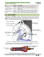
(Figure 4-4a or Figure 4-4b, above) and insert a NPT-to-barbed adapter fitting.
4.
Attach one end of the plastic tubing to the barbed fitting and the other end to the 16” W.C.
(4.0 kPa) manometer.
5. Remove the cap from the Pilot pressure regulator and rotate the regulator adjustment
(beneath cap) clockwise (CW) to its highest possible pressure setting.
6.
OPEN
the main gas supply upstream of the unit.
7. Turn
ON
electrical power to the system.
8. Start the boiler in the MANUAL mode. Observe the manometer pressure when the Pilot
solenoid “clicks” open after purge. The manometer should now provide a reading
between
4.6” W.C. and 5.0” W.C.
(1.15 kPa and 1.25 kPa)
.
9. Pull one of the Pilot Flame Detectors out (see Figure 4-1a) and look into the port in the
front plate. You should see the orange glow of the Pilot flame during the ignition trial
period.
NOTE:
If you do
not
see the orange glow, contact AERCO technical support to ascertain the
problem. If you DO see it, proceed to the next step.
10. If the manometer reading is
below
4.6” W.C. (1.15 kPa),
increase the regulator setting by
rotating the adjustment screw clockwise (CW).
11. Repeat steps 8 through 10 until the gas pressure at the outlet of the Pilot Regulator
pressure reads
between
4.6” W.C. and 5.0” W.C.
(1.15 kPa and 1.25 kPa)
on the
monometer.
12. Once the pressure reading is
between
4.6” W.C. and 5.0” W.C. (1.15 kPa and 1.25 kPa)
,
conduct at least three safe Pilot ignitions while observing the observation port. Assure the
igniter lights immediately with a strong orange flame after the Pilot ignition solenoid valve
opens.
NOTE:
Clear any Flame
Loss During Ignition
messages during the tests by pressing the
CLEAR
key on the C-More Controller.
13.
CLOSE
the external gas supply valve.
14.
Disconnect the manometer, tubing and barbed fitting from the 1/4” NPT port hole.
15.
Replace the 1/4” plug where the barbed fitting was removed
16. Replace the Pilot Flame Detector.

