Benchmark 5000-6000 Operation & Maintenance Manual
SECTION 4
– MAINTENANCE
OMM-0118_B
•
GF-203
•
5/9/2019
Technical Support
•
(800) 526-0288
•
Mon-Fri, 8 am - 5 pm EST Page 48 of 148
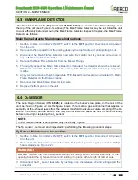
4.7 BURNER INSPECTION
The Burner assembly is located at the front of the unit's heat exchanger. The Burner assembly
may be hot. Therefore, allow the unit to cool sufficiently before removing the Burner assembly.
The following parts will be required for reassembly after Burner inspection:
BMK 750/1000 Burner Inspection Parts
PART NO.
DESCRIPTION
81159
Burner Gaskets (2)
BMK 5000/6000 Burner Inspection Instructions
1. Set the
C-More Control
ler’s ON/OFF switch to the
OFF
position. Disconnect AC power
from the unit and turn off the gas supply.
2. Remove the front panel, top panel and front side panels from the unit by grasping and
lifting straight up and outward. This will expose the blower assembly for removal.
3. Remove the harnesses attached to the C-More Controller, remove 4 nuts (2 above and 2
below) from the C-More bracket and then remove the C-More and set it aside.
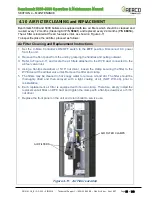
4. Disconnect the lead wire from the Main Flame Detector installed on the Blower Flange
(Figure 4-1a, above).
5. Remove the Main Flame Detector from the Blower Flange.
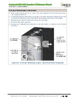
6. Remove the Pilot sensors and observation ports from the Burner Plate (Figure 4-5a,
below).
7. Disconnect the cable from the Pilot Burner by pulling straight out.
8.
Using a 1/2” open-end wrench, disconnect the Pilot gas line from the reducer fitting and
elbow shown in Figure 4-1a. Remove the reducer fitting and then the elbow from the Pilot
Burner.
9. Next, loosen and remove the Pilot Burner from the Burner Plate using a 1-1/2" open-end
wrench.
10. Remove the blower support turn-buckle (Figure 4-5a or Figure 4-5b).
11. Attach a hoist rig capable of lifting at least 300 pounds to the lifting lug on the blower fan
housing.
The Blower assembly weighs approximately 150-200 lbs
.
lbs. depending on
which blower motor is installed
.
12. Remove the two inlet air filters from the galvanized WYE-duct.
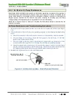
13. Disconnect the wires from the Blower Proof and Blocked Inlet switches (Figure 4-5b).
14. Disconnect the Molex connector from the temp sensor.
15. Place a support block of any appropriate material (such as a scrap 2X4 cut to length) under
the gas train (see Figure 4-5b), and then remove the four 5/8-11 bolts & washers
connecting the gas train to the Air/Fuel valve.
16. Remove the 6 3/8-16 nuts attaching the Air/Fuel valve to the Blower and then pull the
Air/Fuel valve off and set it aside.
17.
Loosen and remove the eight (8) 3/8” hex nuts and washers from the Blower Flange where
it is attached to the Burner
’s Front Plate (see Figure 4-5a).


