Benchmark 5000-6000 Operation & Maintenance Manual
SECTION 6
– AERTRIM OPERATION
OMM-0118_B
•
GF-203
•
5/9/2019
Technical Support
•
(800) 526-0288
•
Mon-Fri, 8 am - 5 pm EST Page 83 of 148
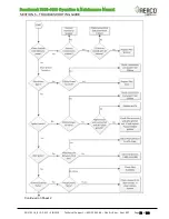
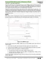
Figure 6-3 graphically shows the functional logic of the AERtrim system and how the blower
voltage (BV), O
2
Limits, and air/fuel ratio interact during an AERtrim operation. The limits are
fixed presets within the controller. The target range is adjustable within these limits to allow the
user to select the optimal air/fuel ratio for a particular boiler or application.
Figure 6-3 shows how the controller would react to an O
2
% reading above the upper limit. The
controller will reduce the blower voltage (BV) until the O
2
% reading is within the Target Range,
provided the BV adjustments are within the BV limits for that unit at that fire rate. The control will
then store this as the new BV calibration setting until changed manually or by another cycle of
the AERtrim function.
NOTE:
When the O
2
sensor is off during the 10 hour O
2
Sensor OFF periods shown above, Modbus
sends an Oxygen Level
of
99
(rather than 0) to building automation system via ProtoNode.
Figure 6-3: AERtrim Logic
Once the system operational stability conditions are met, the AERtrim system will execute the
following steps:
1. Lock the fire rate at the current position that needs adjustment to the air/fuel ratio.
2. The Demand LED will flash once per second
to indicate that the trim function has started.
3. Check the oxygen levels inside the combustion chamber:
•
If oxygen levels are within the set range, AERtrim releases control.
•
If oxygen levels are outside the set range, AERtrim will adjust Blower Voltage to bring
the boiler back to the Target O
2
value.
This process repeats until the target oxygen range is achieved or the unit reaches the allowable
blower voltage limit.

