Benchmark 5000-6000 Operation & Maintenance Manual
SECTION 4
– MAINTENANCE
OMM-0118_B
•
GF-203
•
5/9/2019
Technical Support
•
(800) 526-0288
•
Mon-Fri, 8 am - 5 pm EST Page 51 of 148
4.8 REFRACTORY REMOVAL & REPLACEMENT
WARNING!
The heat exchanger insulation utilizes ceramic fiber material. Wear a fitted NIOSH-approved
particulate respirator (3m n95 or equiv.) When servicing the heat exchanger and burner
assemblies. At high temperatures, ceramic fibers can be converted to crystalline silica fibers,
which have been identified as carcinogenic when inhaled.
Low mass, fiber-based material insulates the front and rear end plates of the combustion
chamber. This material has very low thermal conductivity and is not susceptible to thermal
shock conditions that cause failures of hard-faced refractory materials.
In the event that access to the unit’s combustion chamber is required, the preferred method is to
remove the rear refractory first, since it is much a less complicated procedure; removing the
front refractory requires first removing the blower, burner and air/fuel valve assemblies before
reaching the refractory material.
The procedures for removal of the rear refractory and front refractory materials are provided in
Sections 4.8.1 and 4.8.2, respectively.
4.8.1 Rear Refractory Removal and Replacement
Rear Refractory Replacement Instructions
1. Turn off gas and electrical power to the unit. In addition, turn off any other units sharing the
exhaust flue.
2. Disconnect the flue from the exhaust manifold of the boiler being serviced and remove flue
sections up to the top of the unit enclosure.
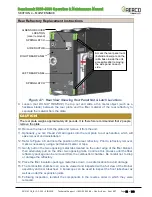
3. Remove the small O
2
Sensor cover panel from the left-rear panel. The Air Eductor
assembly is clipped to the bottom edge of this opening. Lift the Air Eductor assembly up off
the left-rear panel, then secure it in place with a length of cord or wire.
DO NOT
REMOVE
THE LEFT-REAR PANEL
without first securing the Air Eductor assembly in place.
NOTE:
At the top, the left and right-rear panels are attached to the left and right top rails by nuts. At
the bottom, each rear panel is attached to the base with one nut each. Access the nuts for
removal through the side panel, as shown in Figure 4-7.
4. Remove the left-
rear panel, which is held in place by 2 spring latches and 7/16” bolts,
inside the panel on the top rail and bottom lip. See Figure 4-7, below.
5. With the panels removed, the rear plate of the combustion chamber can be accessed as
shown in Figure 4-8, below.
CAUTION!
The surfaces of the heat exchanger may be hot. Allow the unit to cool sufficiently before
proceeding to the next step.
6.
Remove the O2 sensor and the 1/4” stainless steel tube from the rear plate.
7. Disconnect the wires from the thermal switch on the rear plate.
8. Remove all of the nuts from the rear plate, EXCEPT for the one at the top of the plate.


