Benchmark Platinum-Edge: Operation-Service Manual
SECTION 3 - START SEQUENCE
OMM-0137_D • GF-211
•
7/16/2019
Technical Support
•
(800) 526-0288
•
Mon-Fri, 8 am - 5 pm EST Page 22 of 146
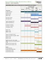
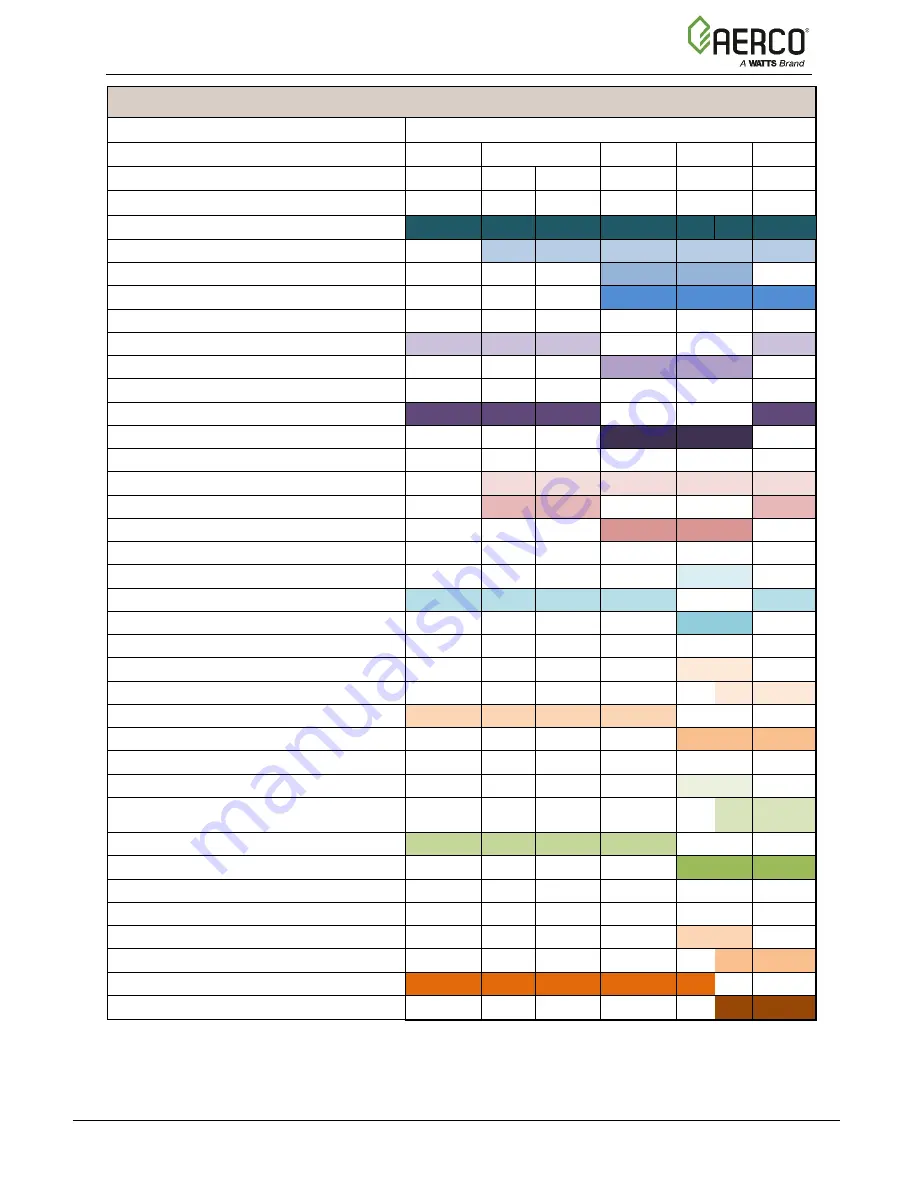
BMK 5000 & 6000 Function Timing Chart For Proved Pilot Control System
Operating State
Pre-purge
PFEP
MFEP
Standby
T = 0
T = 30
T = 37
T = 44
Run
Component
PFEP
MFEP
C-More Controller
Scanner Power
Ignition Power
SSOV Power
Pilot Valve Closed
Pilot Valve Open
Ignition Transformer Off
Ignition Transformer On
UV Scanner Powered
UV Scanner "Ignored"
UV Scanner In Use
Relay 1 Coil
Relay 1 C-NC
Relay 1 C-NO
Relay 2 Coil Power from R1
Relay 2 Coil Power from SKP 15 POC
Relay 2 C-NC
Relay 2 C-NO
SKP15 Power from R1 Contacts
SKP15 Power from R2 contact and POC
C-NO
SKP15 Proof of Closure C-NC
SKP15 Proof of Closure C-NO
SKP25
Power through R1
Power through R2 and AUX
Proof of Closure C-NC
Proof of Closure C-NO

