6
IOM-A-Deringer 40/40X/50/50X_6-8
2005
EDP#2916006
© 2020 Watts
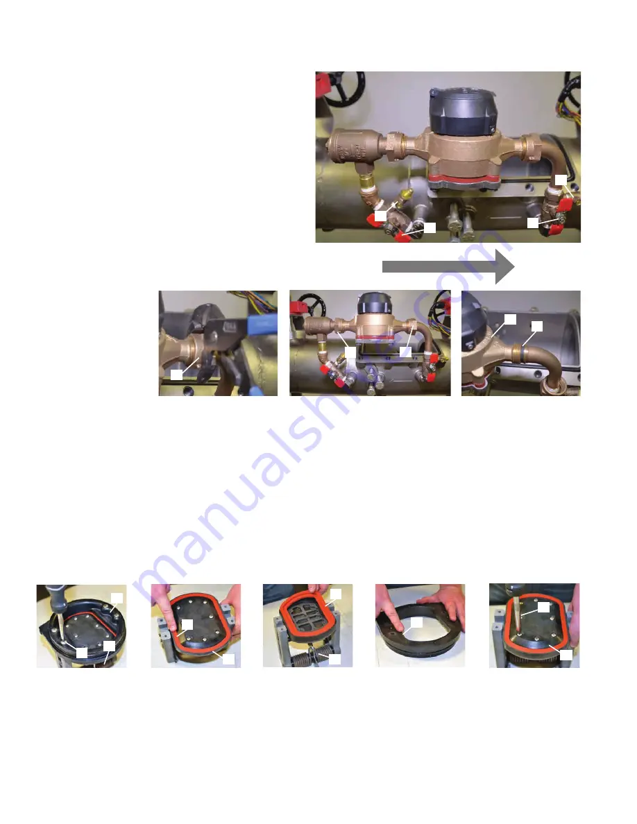
Deringer 50/50X: Removing Bypass Meter
1. Using the ball valve handles close the #2 bypass ball valve
(B) and then #1 bypass ball valve (A). (Ball valve is closed
when “T” handle is perpendicular to water flow through
ball valve).
2. Using a #2 flathead screwdriver open bypass test cock #2
(D) and then open bypass test cock #1 (C). (Test cock is
open when screwdriver slot is parallel to water flow through
test cock).
3. Using large adjustable pliers or a wrench, unscrew and
retract bypass meter coupling nuts (E). Remove the gaskets
(F) on both sides of bypass meter.
4. Gently remove bypass meter (G) from line. It is OK if the
bypass fittings move slightly during the removal process.
5. Reverse order of above instructions to reinstall bypass
meter. Remember to install gaskets (F) before threading
meter coupling nuts into place.
B
C
E
E
G
F
E
FLOW
D
A
Maintenance of First True Seal Check Module
1. Use a #2 phillips head screwdriver to remove tower screws
(A) from the first check seat (B) the double torsion spring
is captured (C) and does not need to be retained
during maintenance.
2. After removing the tower screws (A) examine the elastomer
disk (D) and check seat (E) for fouling or damage.
3. Should elastomer disk (D) need replacement unscrew disk
retainer screws (F) and remove disk retainer (G). Carefully remove
and replace elastomer disk (D). When replacing elastomer disk
(D) be certain that no air, water or debris is trapped in the
clapper (H) cavity behind the elastomer disk (D).
4. Reverse the order of the above instructions to reassemble
check.
• Elastomer disk must be flat in clapper (H) cavity before
tightening disk retainer screws (F).
• Do not cross thread disk retaining screws (F).
• Check orientation is not important when reattaching the
check to the first check seat.
F
G
D
B
A
H
C
D
E
C


