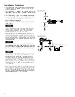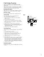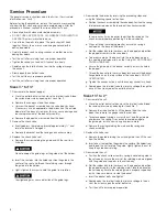
Service Procedure
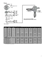
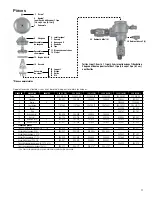
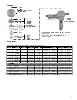
The general service instructions apply to all sizes. (For visual aid
information, see “Parts.”)
Before starting the procedure, remove the freeze sensor mounting
clip from the test cock and set aside to avoid damage. After the
procedure is finished, reattach the clip on either test cock.
• Rinse all parts with clean water before assembly.
• DO NOT USE ANY PIPE DOPE, OIL, GREASE, OR SOLVENT ON
ANY PARTS unless instructed to do so.
• Do not force the parts into place. The parts should fit freely
together. Excess force may cause damage and render the
device inoperable.
• Carefully inspect seals, seating surfaces, and other areas for
damage or debris.
• Test the unit after servicing to ensure proper operation.
• Tighten the canopy nut only until it cannot turn freely.
• Rapidly open the inlet ball valve to minimize spillage through
the air vent.
• Slowly open the outlet ball valve.
• Test the unit to ensure proper operation.
• Test the unit after servicing to ensure proper operation.
Sizes 1/2" to 1¼"
1. Disassemble the bonnet/poppet.
a. Close the outlet ball valve then close the inlet ball valve. Bleed
the residual pressure by opening test cock No. 2.
b. Remove the canopy nut and the canopy.
c. Unscrew the bonnet assembly from the valve body by hand.
(If necessary, use an appropriate-sized wrench on the outside
diameter of the bonnet. However, this may cause damage and
require replacement of the bonnet assembly.)
d. Remove the poppet/seal assembly from the body.
2. Remove the check valve.
a. Evenly depress the retaining bracket approximately 1/4", and
rotate the bracket 90 degrees.
b. Remove the bracket and the spring and check assembly.
3. Replace the check valve seal.
a. Remove the screw holding the guide, and lift the seal from
its holder.
Do not damage the guide legs or the guide pin of the holder.
b. Insert the seal disc into the holder, position the guide in the
center of the seal, and thread the retaining screw through
the guide into the holder.
c. Lightly tighten the screw to hold the guide from rotation.
Overtightening may cause distortion of the guide legs.
4. Reassemble the device by reversing the preceding steps and
using the following special instructions.
a. Position the check assembly into the valve body. Position the spring
into the recessed area on the top side of the check assembly.
In some cases it may be easier to position the spring on the
check assembly before positioning it in the valve body.
b. When installing the retaining bracket, ensure the spring is
centered on the base of the bracket.
c. Roll the rubber disc into the recess on the poppet and position
the poppet assembly in the valve body.
d. To ease assembly of the bonnet into the valve body, apply a
thin coating of petroleum jelly on the O-ring. DO NOT USE ANY
OTHER LUBRICANT.
e. Ensure the guide pin of the bonnet correctly enters the hole in
the poppet.
f. Thread the bonnet into the valve body by hand until the bonnet
flange bottoms on the top surface of the valve body. DO NOT
OVERTIGHTEN.
g. Tighten the canopy nut only until the canopy cannot turn freely.
h. Rapidly open the inlet ball valve to minimize spillage through the
air vent, then slowly open the outlet ball valve.
Sizes 11/2" to 2"
1. Disassemble the unit.
a. Close the outlet ball valve then close the inlet ball valve. Bleed
the residual pressure by opening test cock No. 2.
b. Remove the six bonnet bolts, lift the bonnet from the valve
body, then remove the poppet and the seat disc.
c. To replace poppet spring, unscrew the nut and the guide pin
and remove the spring. Use caution to avoid damage to
the guide pin. Install a new spring and reassemble.
d. Remove the spring retaining the web and the spring and
check assembly.
2. Replace the valve seal.
a. Remove the guide retaining the nut and guide, then lift the seal
from the holder.
b. Insert a new seal, position the guide in the center of the holder/seal,
and thread the nut to retain the guide. Lightly tighten the nut to
keep the guide from rotating.
3. Reassemble the unit.
a. Position the check valve assembly, spring, and retaining web in
the valve body. Ensure the arms of the retaining web are aligned
with the guide and supports in the valve body.
b. Roll the rubber disc into the recess on the poppet and position
the poppet assembly in the retaining web. Place the bonnet on
the valve body. Ensure the retaining web is properly supported
by the three case bosses inside the bonnet.
c. Insert the bonnet bolts and tighten.
d. Rapidly open the inlet ball valve to minimize spillage in the air
vent, then slowly open the outlet ball valve.
e. Test the unit to ensure proper operation.
4


