background image

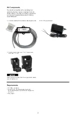
Install the Flood Sensor and Activation Module 

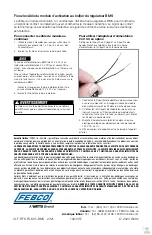
The activation module receives a signal from the sensor when a discharge is detected. If the discharge 

meets the conditions of a qualifying event, the normally open contact is closed to provide a signal to 

the BMS input terminal. 

Custom Flood Sensor Settings 

The default settings on the activation module for detecting discharge are suitable for 

the assembly series. However, the DIP switches can customized for a different wet 

threshold and time delay. Scan the QR code for more information. 

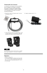
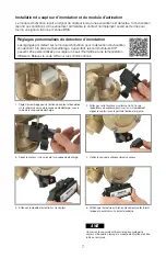
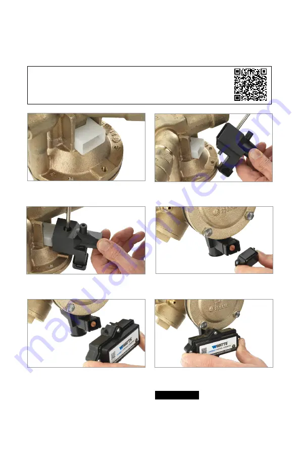
1.  Set the assembly for attachment of the flood sensor to the 

rim of the relief valve body, beneath the relief valve outlet. 

2.  Thread the #2 Phillips screwdriver through the sensor 

adapter to the captive screw and align the sensor with 

the rim attachment point. 

3.  Tighten the sensor to the relief valve body. 

4.  Remove the dust cover from the sensor. 

5.  Press the activation module onto the sensor. 

6.  Check that the module is fully seated to seal the O-ring and 

to make electrical contact. 

NOTICE


Retain the dust cover to protect the flood sensor when the 

activation module needs to be removed or replaced. 

Summary of Contents for FEBCO LF825Y Series

Page 1: ...entryPlus Alert technology does not replace the need to comply with all required instructions codes and regulations related to the installation operation and maintenance of the backflow preventer to w...

Page 2: ...427 A Activation module with 8 conductor cable and ground wire B 24V DC power adapter C Small sensor for valve sizes 3 4 to 1 large sensor valve sizes 1 to 2 NOTICE When installing an air gap attach t...

Page 3: ...wet threshold and time delay Scan the QR code for more information 1 Set the assembly for attachment of the flood sensor to the rim of the relief valve body beneath the relief valve outlet 2 Thread t...

Page 4: ...one year from the date of original shipment In the event of such defects within the warranty period the Company will at its option replace or recondition the product without charge THE WARRANTY SET F...

Page 5: ...la technologie SentryPlus Alert ne remplace pas la n cessit de se conformer toutes les instructions tous les codes et tous les r glements requis li s l installation au fonctionnement et l entretien d...

Page 6: ...re B Adaptateur d alimentation 24 V CC C Petit capteur pour les dimensions de robinet de 3 4 pouce 1 9 cm 1 pouce 2 5 cm grand capteur dimensions de robinet de 1 pouce 3 2 cm 2 pouces 5 1 cm AVIS Lors...

Page 7: ...rents Balayez le code QR pour plus d informations 1 R glez l assemblage pour la fixation du capteur d inondation sur le rebord du corps de la soupape de d charge sous la sortie de la soupape de d cha...

Page 8: ...r une p riode d un an compter de la date d exp dition d origine Si une telle d faillance devait se produire au cours de la p riode sous garantie la Soci t pourra sa discr tion remplacer le produit ou...

Page 9: ...idad de cumplir con todas las instrucciones la normas y los reglamentos necesarios relacionados con la instalaci n la operaci n y el mantenimiento del dispositivo de prevenci n de contraflujo al que e...

Page 10: ...44 m y cable de tierra B Adaptador de alimentaci n de 24 V C Sensor peque o para tama os de v lvula de 3 4 in a 1 in 1 9 cm a 2 5 cm sensor grande tama os de v lvula de 1 in a 2 in 3 17 cm a 5 08 cm...

Page 11: ...tiempo diferentes Escanee el c digo QR para obtener m s informaci n 1 Ajuste el ensamblaje para conectar el sensor de inundaci n al borde del cuerpo de la v lvula de alivio debajo de la sali da de la...

Page 12: ...ial y la mano de obra cuando se usen en forma normal durante un periodo de un a o a partir de la fecha de env o original En caso de que tales defectos se presenten dentro del per odo de garant a la Co...

Reviews: