
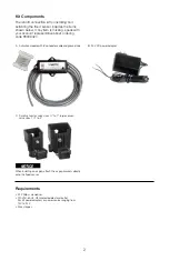

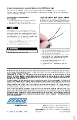
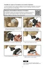
Attach the Activation Module Cable to the BMS Controller
The 4-conductor activation module cable should be attached to the BMS controller to transmit a
normally open contact signal and provide power to the activation module. The contact signal closes
when a discharge is detected.
To connect the module cable to
the controller
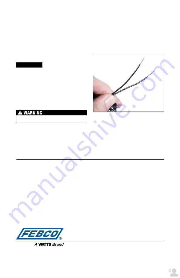
1. Use the wire stripper to cut away enough insulation to
expose 1 to 2 inches of the conductor wires.
2. Insert the white and green wires into the input terminal.
NOTICE
Either the BMS power source (ranging from 12V to 24V)
or the 24V DC power adapter provided can be used. With
each power source, an earth ground connection is required.
If using the optional power adapter, skip to the next set of
instructions. Be sure to use the ground wire provided if there
is no other earth ground on the BMS controller.
Insert the red wire in the power terminal. (A power source
ranging from 12V to 24V is required.)
3. Insert the black wire in the ground terminal.
The earth ground must be connected to the BMS controller
before the flood sensor is put in operation.
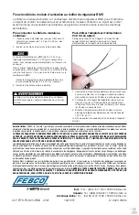
To use the optional 24V DC power adapter
Distinguish the positive wire from the negative one. The
positive wire has white stripes and must be inserted into the
power terminal; the negative wire, into the ground terminal.
1. Connect the positive power adapter wire (black with white
stripe) to the red wire of the activation module cable and
insert the wires into the power terminal.
2. Connect the negative power adapter wire (black with no
stripe) to both the black wire of the activation module
cable and the ground wire (if needed) then insert the
wires into the ground terminal.
3. Plug the power adapter into a 120VAC, 60Hz,
GFI-protected electrical outlet.
4. The flood sensor LED is steady green when the unit
is ready.
Limited Warranty:
FEBCO (the “Company”) warrants each product to be free from defects in material and workmanship under normal usage for
a period of one year from the date of original shipment. In the event of such defects within the warranty period, the Company will, at its option,
replace or recondition the product without charge.
THE WARRANTY SET FORTH HEREIN IS GIVEN EXPRESSLY AND IS THE ONLY WARRANTY GIVEN BY THE COMPANY WITH RESPECT TO THE
PRODUCT. THE COMPANY MAKES NO OTHER WARRANTIES, EXPRESS OR IMPLIED. THE COMPANY HEREBY SPECIFICALLY DISCLAIMS
ALL OTHER WARRANTIES, EXPRESS OR IMPLIED, INCLUDING BUT NOT LIMITED TO THE IMPLIED WARRANTIES OF MERCHANTABILITY
AND FITNESS FOR A PARTICULAR PURPOSE.
The remedy described in the first paragraph of this warranty shall constitute the sole and exclusive remedy for breach of warranty, and the
Company shall not be responsible for any incidental, special or consequential damages, including without limitation, lost profits or the cost of
repairing or replacing other property which is damaged if this product does not work properly, other costs resulting from labor charges, delays,
vandalism, negligence, fouling caused by foreign material, damage from adverse water conditions, chemical, or any other circumstances over
which the Company has no control. This warranty shall be invalidated by any abuse, misuse, misapplication, improper installation or improper
maintenance or alteration of the product.
Some States do not allow limitations on how long an implied warranty lasts, and some States do not allow the exclusion or limitation of inci
dental or consequential damages. Therefore the above limitations may not apply to you. This Limited Warranty gives you specific legal rights,
and you may have other rights that vary from State to State. You should consult applicable state laws to determine your rights.
SO FAR AS
IS CONSISTENT WITH APPLICABLE STATE LAW, ANY IMPLIED WARRANTIES THAT MAY NOT BE DISCLAIMED, INCLUDING THE IMPLIED
WARRANTIES OF MERCHANTABILITY AND FITNESS FOR A PARTICULAR PURPOSE, ARE LIMITED IN DURATION TO ONE YEAR FROM THE
DATE OF ORIGINAL SHIPMENT.
USA:
T: (800) 767-1234 •
•
•
Canada:
T: (888) 208-8927 FEBCOonline.ca
Latin America:
T: (52) 55-4122-0138 FEBCOonline.com
IS-F-RFK-FS-825-BMS 2321
1923057
© 2023 Watts


