


2
Installation Guidelines
NOTICE
The flange gasket bolts for the gate valves should be
retightened during installation as the bolts may have loosened
due to storage and shipping.
1. Consult local codes for specific installation requirements and
restrictions applicable to your area. At least 20 psi (133 kPa) is
recommended for system supply pressure.
2. Install the valves only in the orientation or flow direction shown.
These instructions apply only to Series LF860 and LF866,
sizes 2½" to 10".
3. Install the valve assembly where it is accessible for periodic
testing and maintenance. Clearances shown in the installation
views apply to interior, and pit or vault installations and are
only recommendations. (See Figures 1 and 2.) These mini-
mums do not apply to removable protective enclosures. Refer
to local codes for actual requirements of the area.
4. Before installing the valve into the line, flush the supply line of
all foreign materials. Failure to flush the supply line can cause
the check valves to become fouled and require disassembly
and cleaning.
5. Do not lift the assembly by connecting to the gate valve hand-
wheels or stems.
6. After installation, slowly fill the assembly with water and bleed
air from the body using test cocks No. 2, No. 3, and No. 4.
Test the valve assembly to ensure correct operation.
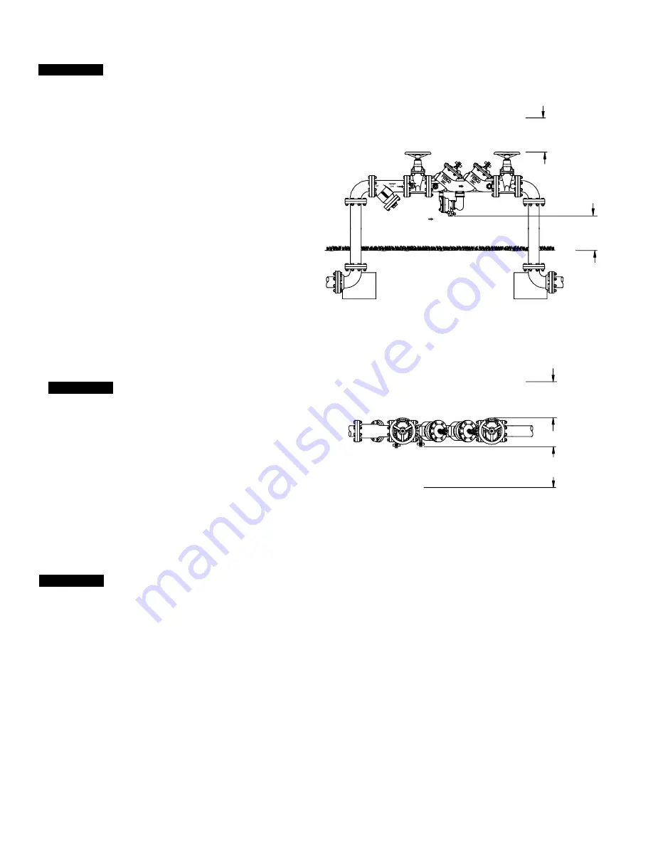
Figure 1
Figure 2
12" min.
Refer to Local
Codes
FLOW
Horizontal Installation
(Shown with strainer)
Horizontal Installation
(Top view, shown with strainer)
18" min.
Refer to Local Codes
12" min.
Refer to Local Codes
6" min.
Refer to Local
Codes
Typical Installation
NOTICE
The gap drain is not designed to catch the maximum discharge
possible from the relief valve. The installation of a FEBCO
®
air
gap with the drain line terminating above a floor drain handles
any normal discharge or nuisance spitting through the relief valve.
However, floor drain size may need to be designed to prevent
water damage caused by a complete failure condition. Do not
reduce the size of the drain line from the air gap fitting.
When installing an air gap, attach the air gap brackets directly
onto the flood sensor.
NOTICE
All assemblies are tested at the factory for proper operation
and leakage. If the valve does not pass the field test, it is most
likely due to a fouled check valve. This is not covered by the
factory warranty. The valve cover(s) must be removed and the
check seats inspected and cleaned. Any damage or improper
operation caused by pipeline debris or improper installation/
start-up is not included in the factory warranty. In case of a
possible warranty claim, contact the local supplier or FEBCO
representative. Do not remove the valve assembly from
the pipeline.
7. Protect the assembly from freezing and excessive pressure
increases. Pressure increases can be caused by thermal
expansion or water hammer. These excessive pressure
situations must be eliminated to protect the valve and system
from possible damage.


