


3
Service and Maintenance
• Rinse all parts with clean water before reassembly.
• Do not use any pipe dope, oil, grease, or solvent on any parts
unless instructed to do so.
• Do not force parts. Parts should fit together freely. Excess force
can cause damage and render the assembly inoperable.
• Carefully inspect seals and seating surfaces for debris or damage.
• After servicing, repressurize the assembly and test to ensure
proper operation.
For more information on maintenance, check with your FEBCO
representative or go to FEBCOonline.com.
Check Valve Disassembly
1. Close the outlet shutoff valve, then close the inlet shutoff valve.
Bleed residual pressure from the assembly by opening test
cocks No. 4, No. 3, and No. 2 in this sequence.
2. Remove the cover nuts and bolts and lift the cover from
the body. The springs are retained and the cover should be
pushed away from the body approximately 1/4 inch.
3. Inspect the parts and debris from the disc and seat ring.
Replace worn or damaged parts as required.
4. Replace the cover, making sure the spring assembly is
positioned in the pivot socket. If necessary, apply FDA
Approved grease to the O-ring groove in the body to keep
the O-ring in position while installing the cover.
5. Install the bolts and nuts and tighten.
PROBLEM
CAUSE
SOLUTION
Continuous relief valve discharge
Debris on check seating surfaces
Disassemble and clean
Debris on relief valve surfaces
Intermittent relief valve discharge
Inlet pressure fluctuations
Eliminate fluctuations
Downstream pressure surges
Eliminate surges
Low flows passing through mainline valve (RPDA)
Mainline check fouled
Disassemble and clean
Troubleshooting
Add-on and Retrofit Sensor Connection Kits for Building Management Systems
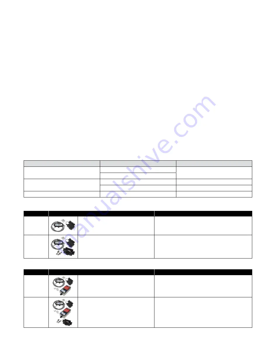
ORDERING CODE
ADD-ON/RETROFIT KIT
DESCRIPTION
88009414
FP-FBF-BMS-21/2-10
BMS Sensor Connection Kit
Series LF860 Large, LF866, LF880V, LF886V
Sizes 2½" to 10"
Includes sensor activation module with cable, ground wire, and power
adapter. Use this kit to activate the flood sensor and enable flood detection
capabilities on the relief valve of a new installation linked to a BMS controller
(not included).
88009415
FP-RFK-FBF-BMS-CFS-21/2-10
BMS Sensor Retrofit Connection Kit
Series LF860 Large, LF866, LF880V, LF886V
Sizes 2½" to 10"
Includes flood sensor with mounting hardware, sensor activation module
with cable, ground wire, and power adapter. Use this kit to install the flood
sensor and enable flood detection capabilities on the relief valve of an exist-
ing installation linked to a BMS controller (not included).
Add-on and Retrofit Sensor Connection Kits for Cellular Communication
ORDERING CODE
ADD-ON/RETROFIT KIT
DESCRIPTION
88009416
FP-FBF-CFS-21/2-10
Cellular Sensor Connection Kit
Series LF860 Large, LF866, LF880V, LF886V
Sizes 2½" to 10"
Includes sensor activation module with cable, Cellular Gateway with mount-
ing kit, ground wire, and power adapter. Use this kit to activate the flood
sensor and enable flood detection capabilities on the relief valve of a new
installation linked to a cellular network to send alerts by email message,
SMS text message, or voice call.
88009417
FP-RFK-FBF-CFS-21/2-10
Cellular Sensor Retrofit Connection Kit
Series LF860 Large, LF866, LF880V, LF886V
Sizes 2½" to 10"
Includes flood sensor with mounting hardware, sensor activation module
with cable, Cellular Gateway with mounting kit, ground wire, and power
adapter. Use this kit to install the flood sensor and enable flood detection
capabilities on the relief valve of an existing installation linked to a cellular
network to send alerts by email message, SMS text message, or voice call.
Relief Valve Disassembly
1. Detach the activation module, if installed, from the flood sensor.
2. Use two ½" wrenches to remove the sensor from the relief valve.
3. Remove the cap screws holding the cover to the relief valve
body, and remove the cover.
4. Remove the diaphragm and pull the internal assembly from
the body. If helpful, push the internal assembly with fingers
through the discharge opening.
5. Inspect for debris, damage, or fouling of the seat disc. Clean
or replace parts as required.
6. Reassemble in the reverse order of disassembly.
Test Procedure for Reduced Pressure Assemblies
Check the ASSE Series 5000 manual for an appropriate test
method that is consistent with local codes of the area.


