10
5.
System configuration
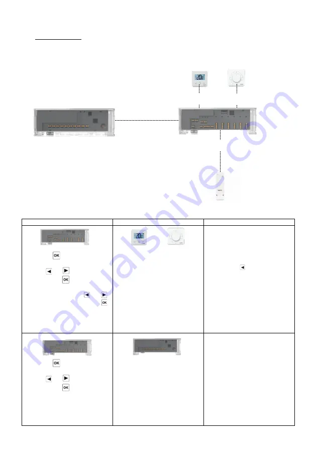
5.1 System configuration without central unit
5.1.1 Standalone installation
Only one controller or multiple controllers without interconnection
Device 1
Device 2
Remarks
By pressing
for 5 seconds, the
controller goes in RF pairing menu.
Bu using and
select zone 1
(Red led), press
to enter in
Pairing with thermostat mode.
Choose the channels with and .
Select/deselect the zone with .
Cursor is blinking green (Zone LED).
Selected zone is fix red.
Already paired zone is fix green.
Thermostats :
Put product in RF pairung mode (refer
to corresponding instruction manual)
If RF pairing is done, the leds of the
channels selected on the WFHC 02
HC RF must turn Green and the
thermostats must exit the pairing
mode.
Exit of the controller pairing menu:
Long press on
By pressing
for 5 seconds, the
controller goes in RF pairing menu.
Bu using and
select zone 3
(Red led), press
to enter in
Pairing with a slave device mode.
All LEDs are blinking red.
Put the device in RF pairing mode.
When link is done WFHC 02 HC RF
and WFHC HCM 02 RF 230 return to
normal mode.
REMARK
: only one WFHC HCM 02
RF 230 per installation
WFHC 02 HC RF
WFHC HCM 02 RF 230 (Option)
BT-WR02 RF (Option)
BT-D03 RF
BT-A03 RF
Summary of Contents for WFHC 06Z 02 HC RF 24
Page 2: ...2 USER GUIDE GB...


