background image

Wattstopper


®

Power Pack
Bloc d’alimentation
Fuente de alimentación

Installation Instructions • Instructions d’Installation • Instrucciones de Instalación

No: 24577 – 11/17  rev. 3

Catalog Number • Numéro de Catalogue • Número de Catálogo: BZ-150

Country of Origin: Made in China • Pays d’origine: Fabriqué en Chine • País de origen: Hecho en China

BZ-150-U is BAA and TAA compliant (Product produced in the U.S.)

SPECIFICATIONS

Voltages ...........................................120/277VAC,50/60Hz
 

 ..................... 230/240 VAC (Single Phase), 50/60Hz

Load Requirements
 

Ballast, Incandescent ............ 20amp @120/277VAC

 Eballast ........................................ 16amp @277VAC
 Motor ......................................... 1HP @120/240VAC
Output .................225mA @24VDC (with relay connected)
Low Voltage Input
 

Control ON  ...............................................12-24VDC


Hold ON  .................................................. 12-24VDC


Hold OFF  ................................................. 12-24VDC


Manual ON (momentary switch required) ... 12-24VDC

Operating Temperature .......................32°-104°F (0-40°C)

DESCRIPTION

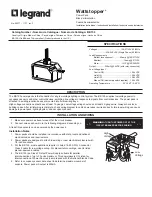
The BZ-150 power packs is the foundation for any low voltage lighting control system. The BZ-150 supplies low voltage power to 

occupancy sensors and other control devices, switching line voltage in response to signals from control devices. The power pack is 

attached to existing junction boxes or mounted into fixture wiring trays.
High voltage connections should use at least 14-gauge. Low voltage wiring should use at least 22-gauge wire. Always check local 

building codes. After initial wiring is complete, check wiring diagram to verify power pack is wired correctly. Improper wiring can cause 

damage to power pack, lighting system, and occupancy sensor.

INSTALLATION AND WIRING

1.  Make sure power has been turned off at the circuit breaker. 
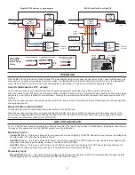
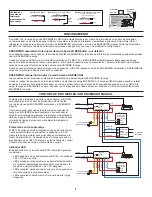
2.  Connect wires as shown in in the following diagrams, depending on 

application.

At least three sensors can be powered by the power pack.

Installation Notes

1.  Power packs should be installed in accordance with state, local and national 

electrical codes and requirements.

2.  Power packs are designed to attach to existing or new electrical enclosures with 

1/2 inch knockouts.

3.  For the BZ-150, most applications require UL listed, 18-22 AWG, 3-conductor, 

Class 2 cable for low voltage wiring. For plenum return ceilings, use UL listed 

plenum-approved cables.

4.  The BZ-150 is a Class 2 Output Power Supply, suitable for parallel 

interconnection of up to 10 units maximum. This powerpack is UL Listed for 

Interconnection of Power Sources in accordance with the National Electric Code.

5.  Refer to occupancy sensor data sheet to determine maximum number of 

sensors. Power pack mA output is 225mA.

WARNING:

 TURN THE POWER OFF AT THE 

CIRCUIT BREAKER BEFORE WIRING.

Low

Voltage

High 

Voltage

Summary of Contents for BZ-150

Page 1: ...use at least 14 gauge Low voltage wiring should use at least 22 gauge wire Always check local building codes After initial wiring is complete check wiring diagram to verify power pack is wired correctly Improper wiring can cause damage to power pack lighting system and occupancy sensor INSTALLATION AND WIRING 1 Make sure power has been turned off at the circuit breaker 2 Connect wires as shown in ...

Page 2: ...load with the next input from the occupancy sensor Manual ON Mode Switch RIGHT Occupants must press the low voltage momentary switch to turn ON the load When the occupancy sensor is the only input keeping the load ON the load turns OFF when the sensor s time delay expires If the sensor input re triggers within 30 seconds after the load turns OFF the load turns ON again After 30 seconds expire with...

Page 3: ...esentation The BZ 150 is set for the Auto ON Mode and the occupancy sensor time delay expired The BZ 150 reverted to Auto ON and then motion was detected Consider increasing occupancy sensor sensitivity and or time delay Generate more motion during presentations The load does not turn ON with occupancy detection Mode Switch is set to Manual ON Hold OFF input is active The load does not turn OFF af...

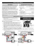
Page 4: ... l installation 1 Les blocs d alimentation doivent être installés conformément aux codes de réglementation électrique et exigences régionaux et nationaux 2 Les blocs d alimentation sont conçus pour être raccordés à des coffrets électriques neufs ou déjà existants dotés de débouchures de 12 7 mm 0 5 po 3 Pour le BZ 150 dans le cas d un câblage à faible tension la plupart des applications nécessiten...

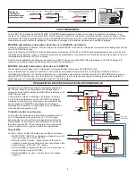
Page 5: ...momentané basse tension pour ACTIVER la charge Lorsque le détecteur de présence constitue la seule entrée qui maintient la charge ACTIVE la charge se COUPE à la fin de la temporisation du détecteur Si l entrée du détecteur se re déclenche dans les 30 secondes qui suivent la COUPURE de la charge la charge s ACTIVE de nouveau À la fin du délai de 30 secondes si le bloc ne reçoit aucun signal d entré...

Page 6: ...ralise les entrées MARCHE de régulation maintien de l état MARCHE et maintien de l état ARRÊT DÉPANNAGE Les lumières s ALLUMENT automatiquement après que vous les ayez volontairement COUPÉES pour une présentation Le BZ 150 est réglé sur le mode MARCHE automatique et la temporisation du détecteur de présence s est écoulée Le BZ 150 est revenu sur MARCHE automatique et des mouvements ont été détecté...

Page 7: ...es sensores Notas de la instalación 1 Las fuentes de energía deben instalarse según los códigos y requisitos eléctricos estatales locales y nacionales 2 Las fuentes de energía están diseñadas para conectarse a gabinetes eléctricos nuevos o existentes con troqueles de pulgada 3 Para el BZ 150 la mayoría de las aplicaciones requieren cables certificados por UL de calibre 18 a 22 de 3 conductores de ...

Page 8: ...omentáneo de bajo voltaje para ENCENDER la carga Cuando el sensor de ocupación es la única entrada que mantiene la carga ENCENDIDA la carga se APAGA cuando expira el retardo de tiempo del sensor Si la entrada del sensor se vuelve a activar dentro de un plazo de 30 segundos después de que se APAGA la carga la carga se ENCIENDE de nuevo Si pasan los 30 segundos sin entrada del sensor presione el int...

Page 9: ...n anula las entradas del Control ENCENDIDO Mantener ENCENDIDO y Mantener APAGADO SOLUCIÓN DE PROBLEMAS Las luces se ENCENDIERON automáticamente después de haberlas APAGADO deliberadamente para una presentación El BZ 150 está configurado para el Modo de ENCENDIDO automático y expiró el retardo de tiempo del sensor de ocupación El BZ 150 se revirtió a ENCENDIDO automático y luego se detectó movimien...

Page 10: ...10 ...

Page 11: ...11 ...

Page 12: ...éfauts de matériaux et de fabrication pour une période de cinq 5 ans Wattstopper ne peut être tenu responsable de tout dommage consécutif causé par ou lié à l utilisation ou à la performance de ce produit ou tout autre dommage indirect lié à la perte de propriété de revenus ou de profits ou aux coûts d enlèvement d installation ou de réinstallation Wattstopper garantiza que sus productos están lib...

Reviews: