
Quick St
art Guide
MOUNTING AND PLACEMENT
EORS-101
EORS-101/102
EOHR-101/102
WattStopper® Wireless Lighting Control System
EORS Series Wireless Remote Switch
EOHR Series Handheld Remote
Input Voltage: ............ Self-powered when the switch is pressed
Connection to Wireless Network:..................................................
Sends signals to Wall Switches via Radio Frequency
Environment ................................................. For Indoor Use Only
Operating Temperature ....................32° to 131°F (0° to 55°C)
Storage Temperature ...................... 23° to 176°F (-5° to 80°C)
Relative Humidity ...........................5 to 95% (non condensing)
Patent Pending
EORS-102
The EORS and EOHR are low profile wireless self-powered remote switches that can be placed anywhere within range of the system,
up to 150ft in an open space.
PAIRING OF REMOTE SWITCH TO
WALL SWITCH RECEIVER LOAD(S)
Pairing of the remote switch or handheld remote is simply done
by entering pairing mode at the wall switch receiver (EOSW-1x1
or EOSW-1x2) and pressing the
Pairing
button “P” on each device for 3 seconds.
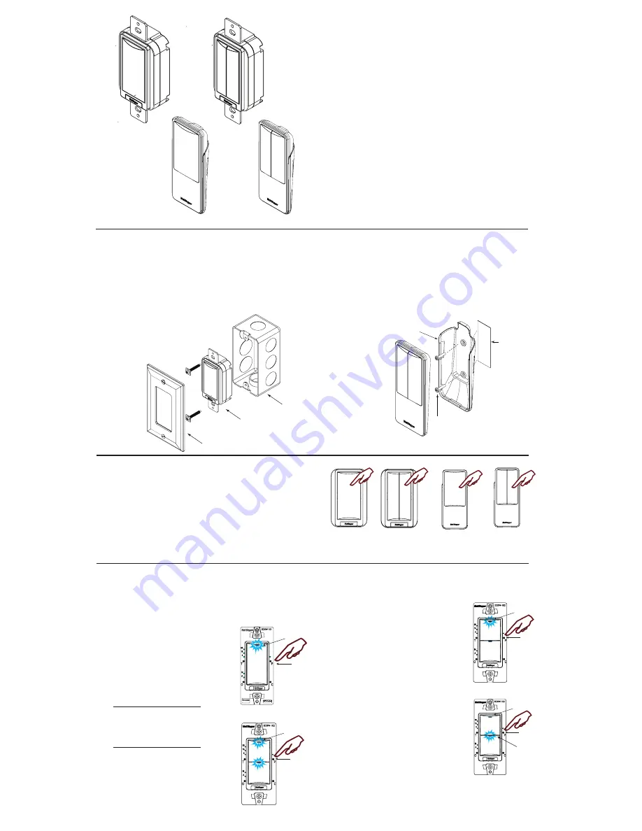
Step 1: Enter Pairing Mode
Press and Hold “Pairing” Button “P” on
Receiver for 3 Seconds then release:
• Pairing LED on the EOSW switch
begins to blink rapidly (2x/second).
This confirms that the Receiver is
now in pairing mode
For EOSW-101/ EOSW-111
• Load 1 turns
ON
and is ready
to be paired
• Load status button LED is Solid ON
For EOSW-102/ EOSW-112
• Load 1 & 2 turn
ON
and are
ready to be paired
• Load status button 1 & 2 LED are
Solid
ON
Step 2: Selecting a Specific Load to Pair (EOSW-102)
*By default, both loads turn On at the same time in Pairing Mode. If both
loads are to be controlled by the Remote
Switch than skip this step.
Tap the “Pairing” Button “P” once
while in pairing mode:
• Load 2 turns
OFF
and Load 1
remains
ON
• Load 1 is now active and ready to be
paired to selected transmitters
• Load 1 LED is Solid
ON
Tap the “Pairing” Button “P” once
again while in pairing mode:
• Load 1 turns
OFF
and Load 2
turns
ON
• Load 2 is now active and ready to
be paired to selected transmitters
• Load 2 LED is Solid
ON
Tap the “Pairing” Button “P” a third
time while in pairing mode:
• Load 1 and Load 2 turn
ON
again, indicating both loads are
ready to be paired.
“Load Status”
Blue LED
Pairing
Button
EOSW-101
EOSW-102
“Load Status”
Blue LED
Pairing
Button
EOHR-101
EOHR-102
POWERUP AND OPERATION
The EORS-10x Wireless Remote Switch and EORS-10x Handheld
Remote are self-powered by harvesting the kinetic impulse of the
physical push of the button.
Once a device is paired with the remote, the EORS and EOHR use
radio frequencies to transmit signals to the wireless system. To
turn load(s) ON/OFF, press the paddle button on the EORS-10x or
EOHR-10x.
EOSW-102
“Load 1 Status”
Blue LED ON
Pairing
Button
EOSW-102
“Load 1 Status”
Blue LED OFF
Pairing
Button
“Load 2 Status”
Blue LED On
EOHR-101
On/Off
button
EOHR-102
EORS-102
EORS-101
Press on the top left
or top right button to
turn load On
Press on the bottom left
or bottom right button to
turn load Off
Press on the top left
or top right button to
turn load On
Press on the bottom left
or bottom right button to
turn load Off
On/Off
button
On/Off
button(s)
On/Off
button(s)
Press on top of button
to turn load On and
press on bottom of
button to turn load Off
Press on top of button
to turn load On and
press on bottom of
button to turn load Off
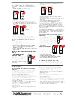
Double-backed
foam tape
Wall Mount
EOHR-102
Use the double-backed
foam tape on the back
of EOHR mounting bracket
to mount to a glass wall
Mounting
Bracket
Slide EOHR onto
mounting bracket
to secure
Use two screws to mount
the EOHR-10x to a hard wall
using the mounting bracket
EORS-101
Junction box
Wall plate
EORS Remote Switch
Secure the EORS Remote Switch to the wall plate and junction
box using two machine screws (included). Please, do not force or
overtorque unit with torque screw driver. To do so may damage the
unit. < 8 in-lb of torque is adequate to secure unit.
Align the sensor in the J-Box so that the
mounting screw tabs on the J-Box match
the key holes on the sensor’s rear housing.
EOHR Handheld Remote
The EOHR can be used as a handheld remote or mounted to
a glass wall using the double-back foam tape on the back of
mounting bracket as shown. It can also be mounted to a hard
wall using two screws and the mounting bracket provided.
Mounting to Hard Wall
1. Drill holes in wall using
the two holes on the
mounting bracket as a
template.
2. Secure the mounting
bracket to the wall using
two machine screws
(included).
3. When finished
slide EOHR onto
mounting bracket.


