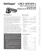
LMLS-400/400-L
Digital Lighting Management
Closed Loop
Single Zone Photosensor
SPECIFICATIONS
Light sensor range .......................................1 to 6,553 fc
Voltage ..................................................................24VDC
Current Consumption ...............max 13mA, typical 3mA
Power Supply ............................ DLM Room Controllers
Connection to the DLM Local Network ........1 RJ45 port
Environment:
Operating Temperature ..... 32° to 131°F (0° to 55°C)
Storage Temperature ...... 23° to 140°F (-5° to 60°C)
Relative Humidity ............ 5 to 95% (non condensing)
Other:
RoHS compliant, 5-year warranty
Dimensions:
LMLS-400/400-L
Length ..................................................... 3.9” (99mm)
Width ....................................................... 1.2” (30mm)
Depth .....................................Minimum 1.0” (25mm)
Maximum 1.5” (38mm)
Tube Diameter .......................................... 0.88” (22mm)
Ceiling Tile Thickness:
LMLS-400 ........................................0” - 5/8” (16mm)
LMLS-400-L ................. 5/8” (16mm) - 1.25” (31mm)
FACTORY DEFAULTS
Switching Operation:
ON Setpoint* .......................................................7.5 fc
OFF Setpoint* ......................................................11 fc
ON Time Delay .................................................. 20 sec
OFF Time Delay ............................................... 10 min
Dimming Operation:
Day Setpoint* .......................................................50 fc
Night Setpoint* ....................................................10 fc
Ramp Rate Up ........................................ 20% per sec
Ramp Rate Down ...................................... 2% per sec
Cut Off Delay ......................................................Never
Advanced Parameters:
Allow Override ........................................................No
Override Time .................................................. Infinity
Hold OFF .................................................................No
Scenes Stop Daylighting ........................................No
Ignore After Hours .................................................No
* Setpoints change automatically upon calibration
UNIT DESCRIPTION
The LMLS-400 is a closed loop photosensor that measures
the ambient light level in order to automatically switch or
dim one zone of lighting. It is part of the Digital Lighting
Management (DLM) system and sends light level signals
to control loads connected to DLM switching or dimming
room controllers. The LMLS-400 has photodiodes
with an extended range of 1-6,553 footcandles (fc), and
photopic correction to mimic the human eye, for precise
measurement of visible light.
The LMLS-400 operates on Class 2 power supplied to a DLM
local network by one or more DLM room controllers.
Plug n’ Go automatic configuration assigns the photosensor
to control load 1. Loads may be reassigned using an
LMCT-100. Following a manual or automatic setup process,
the LMLS-400 monitors the ambient light in the controlled
space and works with the room controller(s) to maintain the
design light level. The LMLS-400 uses switching or dimming
setpoints and other control parameters to manage the light
levels throughout the day regardless of changing daylight
contribution.
Sensor Installation and Configuration Overview
1.
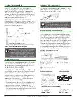
Mount the photosensor so that the Photosensor Viewing Port
views the daylight and electric light combined.
2. Complete all wiring and turn ON power to the room controller.
3. Use the LMCS-100 or LMCT-100 configuration tool to complete the
configuration process.
The LMLS-400 will not operate properly until the
configuration and calibration is successful.
A. Select the LMLS-400 to be configured, from the Daylighting
menu.
B.
Use Zone Setup to select the operating mode for the
controlled zone (Switched, Bi-Level, Tri-Level, or Dimmed).
C. Assign individual loads to the LMLS-400 controlled zone.
D.
Calibrate the LMLS-400 either automatically or manually.
If manual calibration is chosen a light meter will be
required.
E. Adjust Zone Settings and Advanced Settings to meet specific
sequence of operation requirements.
F. Use Test Mode to verify the LMLS-400 operation.
Installation Instructions

