background image

www.wattstopper.com

Page 11

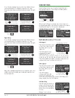
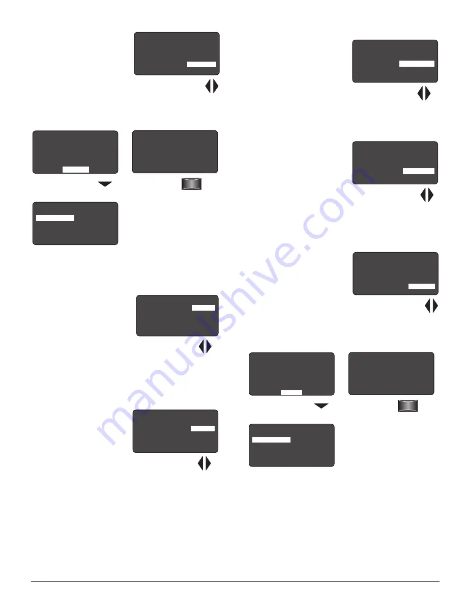
OFF Time Delay 

The time interval that must 

elapse, with the measured 

level above the OFF Setpoint, 

before the controlled lights 

turn OFF.

Range: 3 min to 30 min.

Send 

D a y l i g h t i n g       L M L S - 4 0 0

B i - L e v e l

S E N D

O N   S e t p o i n t :

O F F   S e t p o i n t :

O N   T i m e   D e l a y :

O F F   T i m e   D e l a y :

< 7 . 5 f c >

< 1 1 f c >

< 2 0 s e c >

< 1 0 m i n >

Press the Down Arrow

to choose SEND

Point and

Press Select

L M L S - 4 0 0             0 2 9 3 6 1 1 9 3 5


Z o n e   S e t u p

C a l i b r a t i o n

Z o n e   S e t t i n g s

A d v a n c e d   S e t t i n g s

C o n t r o l   M o d e

LMLS-400 Daylighting Menu

Zone Settings have been saved.  

The screen returns to the Daylighting 

Parameters menu.

P o i n t   t o   a n y   I R  

e n a b l e d   d e v i c e   o n  

t h e   N e t w o r k

P r e s s   ‘ S e l e c t ’

Dimmed

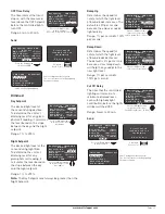
Day Setpoint 

The desired light level at 

the sensor during daytime. 

To determine the correct 

dimming level for any given 

photocell reading, it calculates 

the level based on the slope 

between the day and the night 

setpoint. 

Range: 1 fc to 255 fc.

Night Setpoint 

The desired light level at the 

sensor during nighttime. 

To determine the correct 

dimming level for any 

given photocell reading, it 

calculates the level based on 

the slope between the day 

and the night setpoint. 

Range: 1 fc to 255 fc.

Note:

 The Day Setpoint must always be greater than the 

Night Setpoint.

D a y l i g h t i n g           L M L S - 4 0 0

B i - L e v e l

S E N D

O N   S e t p o i n t :

O F F   S e t p o i n t :

O N   T i m e   D e l a y :

O F F   T i m e   D e l a y :

< 7 . 5 f c >

< 1 1 f c >

< 2 0 s e c >

< 1 0 m i n >

Press Left/Right arrow 

to raise or lower 

OFF Time Delay <3min - 30min>

D a y l i g h t i n g         L M L S - 4 0 0

D i m m e d

S E N D

D a y   S e t p o i n t :

N i g h t   S e t p o i n t :

R a m p   U p :

R a m p   D o w n :

C u t   O f f   D e l a y

< 5 0 f c >

< 1 0 f c >

< 2 0 % / s e c >

< 2 % / s e c >

< 1 0 m i n >

Press Left/Right arrows 

 to increase or decrease

footcandles

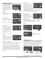
Ramp Up 

Determines the speed (or 

rate) at which the light level 

of bound loads increases. The 

default is 20% per second 

because the end user needs 

light quickly. 

Range: 1% per second to 100% 

per second.

Ramp Down 

Determines the speed (or 

rate) at which the light level 

of bound loads decreases. 

The default is 2% per second 

because a slow ramp down 

will help the eye adapt to the 

new light level.

Range: 1% per second to 

100% per second.

Cut Off Delay 

The time that the controlled 

lighting will remain at a 

minimum dimmed level, 

even with high daylight 

contribution, before the lights 

will be switched OFF. 

Range: Never to 30 min.

Send 

Press the Down Arrow

to choose SEND

Point and

Press Select

L M L S - 4 0 0             0 2 9 3 6 1 1 9 3 5


Z o n e   S e t u p

C a l i b r a t i o n

Z o n e   S e t t i n g s

A d v a n c e d   S e t t i n g s

C o n t r o l   M o d e

D a y l i g h t i n g         L M L S - 4 0 0

D i m m e d

S E N D

D a y   S e t p o i n t :

N i g h t   S e t p o i n t :

R a m p   U p :

R a m p   D o w n :

C u t   O f f   D e l a y

< 5 0 f c >

< 1 0 f c >

< 2 0 % / s e c >

< 2 % / s e c >

< 1 0 m i n >

Zone Settings have been saved.  

The screen returns to the Daylighting 

Parameters menu.

P o i n t   t o   a n y   I R  

e n a b l e d   d e v i c e   o n  

t h e   N e t w o r k

P r e s s   ‘ S e l e c t ’

D a y l i g h t i n g         L M L S - 4 0 0

D i m m e d

S E N D

D a y   S e t p o i n t :

N i g h t   S e t p o i n t :

R a m p   U p :

R a m p   D o w n :

C u t   O f f   D e l a y

< 5 0 f c >

< 1 0 f c >

< 2 0 % / s e c >

< 2 % / s e c >

< 1 0 m i n >

Press Left/Right arrows 

 to increase or decrease

Fade Up time (5sec - 60sec)

D a y l i g h t i n g         L M L S - 4 0 0

D i m m e d

S E N D

D a y   S e t p o i n t :

N i g h t   S e t p o i n t :

R a m p   U p :

R a m p   D o w n :

C u t   O f f   D e l a y

< 5 0 f c >

< 1 0 f c >

< 2 0 % / s e c >

< 2 % / s e c >

< 1 0 m i n >

Press Left/Right arrows 

 to increase or decrease

Cut Off Delay (Never - 30 min)

Summary of Contents for LMLS-400

Page 1: ... 6 553 footcandles fc and photopic correction to mimic the human eye for precise measurement of visible light The LMLS 400 operates on Class 2 power supplied to a DLM local network by one or more DLM room controllers Plug n Go automatic configuration assigns the photosensor to control load 1 Loads may be reassigned using an LMCT 100 Following a manual or automatic setup process the LMLS 400 monito...

Page 2: ...ther than lighting if the load is not in view of a person at all control locations Do not use DLM to control any load that might be dangerous or cause a hazardous situation if accidentally activated Mount photosensor to read both daylight and electric light LMLS 400 Window Light Fixture Typical Daylit Zone about 12 3 6m 100 CONNECT THE LMRJ CABLE The LMLS 400 receives power and communicates with o...

Page 3: ...n Quick press cycle through load binding verification test Press and hold for two seconds start automatic calibration first relinquish load binding verification test if active CONFIG Button Quick press if the system is not presently in PnL mode the red LED will flash once If the system is in PnL mode at the time of the press the system will advance to select the next load on the IRB in sequence Pr...

Page 4: ...until the load is turned off and back on again or until the level is adjusted upwards If a load has been dimmed a single tap on the top of a controlling switch s rocker will return the level to the maximum allowed by daylighting at that time and cancel the level restriction cap set by the earlier user adjustment Increasing the light level above that set by daylighting is possible only if Allow Ove...

Page 5: ...ry charge A warning appears on the display when the battery level falls below a minimum acceptable level To conserve battery power the LMCT 100 automatically shuts off 10 minutes after the last key press Navigation You navigate from one field to another using up or down arrow keys The active field is indicated by flashing alternates between yellow text on black background and black text on yellow ...

Page 6: ...d device o n the network Press Select Point and Press Select Press Select Choose Search Photsensors Dayli g hting LM LS 400 Se lect a d evice I D 0293724909 Press Select Choose Desired Photsensor Point to Any IR enabled device o n the network Press Select Point and Press Select LMLS 400 Daylighting Menu Serial number will be different for each LMLS 400 LMLS 400 0293724909 Zone S etup Calib ration ...

Page 7: ... No NEXT PRIOR DONE Zone settings for the next load is diplayed Zone Setup LMLS 400 Switched Load 1 Daylight Load Yes NEXT PRIOR DONE Zone Setup LMLS 400 Switched Point to an IR enabled device on the Network Press Select Prior To continue to assign Daylight Load binding to the previous load choose PRIOR This function behaves the same for all Operation Modes Point and Press Select Press Select Choo...

Page 8: ...vel reaches the ON Setpoint again the Max assigned load turns ON When the ambient light level reaches the ON Setpoint the Med Max assigned load will turn ON MED OFF Load 1 Med Max Load 2 Max Load 1 Med Max Load 2 Max MED MAX Load 1 Med Max Load 2 Max MAX Load 1 Med Max Load 2 Max Load 1 Med Max Load 2 Max Off Med Max 8AM 0 9AM 10AM 11AM 12AM 1PM 2PM 3PM 4PM 5PM 6PM 7PM 8PM 5 10 15 20 25 30 35 40 4...

Page 9: ... the controlled loads switching ON and OFF then the sensor enters Test Mode for 5 minutes Calibrating LMLS 400 Manual Calibration Press Select Press Select LMLS 400 0293611935 Zone Setup Calibration Zone Settings Advanced Settings Control Mode Choose Manual Calibration Choose Calibration LMLS 400 0293611935 Automatic Calibration Manual Calibration Depending on how the Operation Mode is configured ...

Page 10: ...one Settings When Zone Settings is selected one of two screens is displayed depending on the Operation Mode of the device Switched Bi Level or Tri Level or Dimmed Switched Bi Level or Tri Level Dimmed Switched Bi Level or Tri Level ON Setpoint The target illuminance level at the sensor below which the LMLS 400 turns the lights ON The ON Setpoint values available for manual adjustment are 1 0 1 2 1...

Page 11: ...LMLS 400 Dimmed SEND Day Setpoint Night Setpoint Ramp Up Ramp Down Cut Off Delay 50fc 10fc 20 sec 2 sec 10min Press Left Right arrows to increase or decrease footcandles Ramp Up Determines the speed or rate at which the light level of bound loads increases The default is 20 per second because the end user needs light quickly Range 1 per second to 100 per second Ramp Down Determines the speed or ra...

Page 12: ...o the sensor allows daylighting to adjust light levels up to the level recorded in the Scene even though a scene is active When set to Yes daylighting control is disabled for any loads on which a scene is recalled until a change is manually made to the level of a load in the zone or until the next cycle of occupancy Ignore After Hours Dayl i ght i ng LMLS 40 0 SEND NE XT Li ght Level Al l ow Overr...

Page 13: ...lighting Parameters menu P o in t t o a n y IR e n a b le d d e vic e on t h e N e t wo r k P re s s S e le c t Demo Demo mode will allow the photosensor to select a set of preset parameters This mode should only be selected when demonstrating the functionality of the unit is desired Daylighting LMLS 400 Control Mode Control Mode Demo SEND CANCEL Point and Press Select LMLS 400 0293724909 Zone Set...

Page 14: ...nsor is in an override condition either due to an override from a wall switch or due to an automatic or manual commissioning operation If the latter complete the commissioning operation first otherwise use a wall switch to turn off the controlled loads to terminate the override If the blink is faster one flash every second the photosensor is in Test Mode or Demo Mode Test Mode will cancel automati...

Reviews: