1726 North Ballard Road, Suite 1 - Appleton, WI 54911 - 920.991.9082
Technical Support 855.804.5774 - Parts@waupacaelevator.com
PTM30133-G
22 MAR 2018
W
E
CRUSH
HAZARD
CUTTING
HAZARD
CRUSH
HAZARD
CRUSH
HAZARD
CRUSH
HAZARD
CRUSH
HAZARD
FALLING
HAZARD
CRUSH
HAZARD
KINK
HAZARD
CRUSH
HAZARD
PINCH
HAZARD
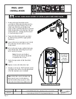
SLING ASSEMBLY AND
SAFETY INSTALLATION
16.
19.
17.
14.
18.
15.
13.
17
Note:
Weight on the sling may be
needed for downward direction.
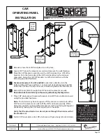
Note:
Verify there is an equal distance from the safety
dogs to the rails on each side.
Torque all 1/2” sling fasteners to 85 ft-lbs
Torque all 3/8” sling fasteners to 44 ft-lbs
13
SERIES :
115, 116, 118
SET SCREWS
ADJUSTMENT PIN
ANTI-ROTATION
BRACKET
LIVE END
ADJUSTMENT
NUTS
3"
1-1/2"
DEAD SIDE
(NON LOAD
BEARING)
WEDGE
LIVE SIDE
(LOAD BEARING)
CABLE
CLAMP
ASSEMBLY
A
B
BOTTOM CROSS
MEMBER PLATE
16
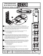
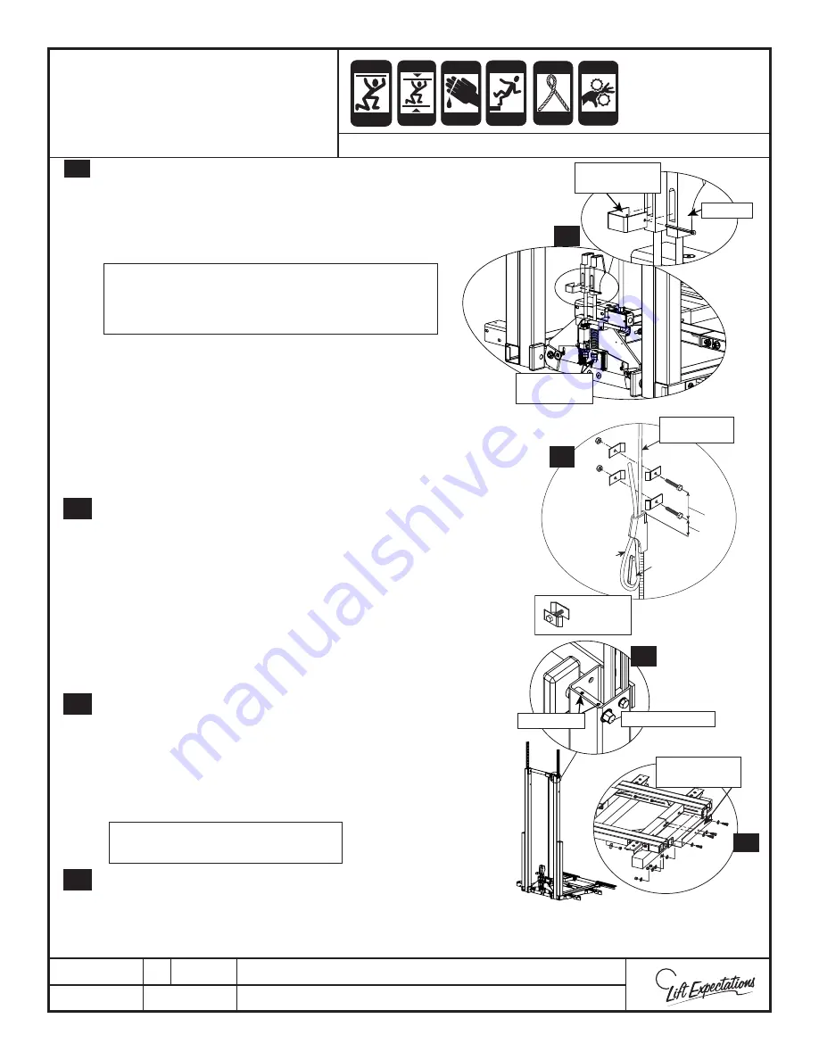
Fasten bottom cross member plate in place with the
following provided hardware:
(4) - 1/2”-13 x 1-1/2” Hex Screws
(4) - 1/2” Flat Washers
(4) - 1/2”-13 Nylock Nuts
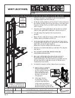
Release the safety by unscrewing the nuts to cotter pin.
The minimum distance the shackle rod must extends
above safety assembly is 2”. This allows the slack cable
switch to trip when cables are slack.
Locate the previously secured wire rope. Unsecured wire
rope one at a time verifying the ropes are not twisted.
Route the wire rope through either of the shackle sockets
while pulling down on the wire rope to seat the shackle
tightly in the pedestal base. Loop the wire rope up back
through the shackle socket while continuing to hold the
tension on the wire rope. Insert the wedge into the newly
formed loop and pull on the dead end of the wire rope
to seat the wedge into the shackle socket. Repeat this
step for the other shackle.
Clamp cable clamps at max. distance of 1-1/2”
Clamp cable clamps at max. distance of 3”
Once shackles are assembled and roped as shown in
safety, place anti-rotation bracket into both shackles,
insert cotter pin, and fl are ends of cotter pin.
Pendant sling up to hang on ropes. Verify the rope
tension is equal and adjust if necessary. Verify that the
safety functions.
Verify that your sling base is level while hanging on the
wire ropes. Adjust as necessary by loosening the top 4
1/4”- 28 set screws that are securing the guide block pins
in position. Rotate guide block pins as necessary to level
sling base and then tighten.
19
Page 26


