1726 North Ballard Road, Suite 1 - Appleton, WI 54911 - 920.991.9082
Technical Support 855.804.5774 - Parts@waupacaelevator.com
PTE10200-A
13 MAR 2018
W
E
Series:
008, 021, 022, 114, 115, 116, 118, 210
RED
BLK
YE
L
RED
BLK
YE
L
RED
BLK
YE
L
RED
BLK
YE
L
RED
BLK
YE
L
RED
BLK
YE
L
RED
BLK
YE
L
RED
BLK
YE
L
RED
BLK
YE
L
9
8
7
6
5
4
3
2
1
Dim
m
er
Blue/ Hot
Black
White
Yellow Dim Control
Red Dim Control
Black Dim Control
To Lights
120-240V
AC FEED
(Switched)
Change
Indicator
Battey
Test
Switch
Power Supply
DC Wiring
Battery
Back
Up
Blue/ Hot
Brown/ Neut
Brown/ Neut
Green & Yellow
LED Light Wiring
(With battery back up wiring)
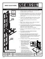
Strip the LED extension cord back to the desired length. Wire per LED light schematic and
national and local codes terminating one LED light per terminal.
Wire 2 LED lights to terminals 8 and 9 for emergency lighting. Wire per LED light schematic
and national/local codes.
Verify that all LED lights work and adjust the dimmer to desired brightness.
Secure the LED Light covers and power supply to the ceiling of the elevator car with provided
hardware
When the installation is complete press the test switch to test light operation. Allow up to 10
hours for a battery to fully charge before testing.
5.
WITH BATTERY BACK-UP WIRING
(OPTIONAL)
1.
2.
4.
3.
WARNING: DO NOT MIX AC AND DC WIRING. MAINTAIN BARRIER AS SHOWN BY THE DOTTED LINE
Input and output conductors are to be insulated for a minimum of 300V for all circuit connections.
CRUSH
HAZARD
CUTTING
HAZARD
CRUSH
HAZARD
CRUSH
HAZARD
FALLING
HAZARD
ANTI-
STATIC
ALERT
NOTE:
THERE ARE 9 SETS OF TERMINAL BLOCKS, EACH WITH 3 CONDUCTORS PER LIGHT. FOR SIMPLICITY, ONLY 1 SET IS SHOWN IN THIS
DIAGRAM. ALWAYS CONNECT ALL 3 WIRES (RED, BLACK, YELLOW), EVEN IF DIMMING IS NOT REQUIRED.
TO TURN LIGHTS ON AND OFF, SIMPLY ENERGIZE OR DE-ENERGIZE THE 120/240V AC INPUT TO THE EL2 POWER BOX.
ATTENTION: REMOVE ALL JUMPERS AS REQUIRED OUT OF THE LED LIGHT CONTROLLER BOX
Page 42


