1726 North Ballard Road, Suite 1 - Appleton, WI 54911 - 920.991.9082
Technical Support 855.804.5774 - Parts@waupacaelevator.com
PTE10010-I
23 FEB 2018
W
E
CRUSH
HAZARD
CUTTING
HAZARD
ELECTRIC
HAZARD
FALLING
HAZARD
CRUSH
HAZARD
PINCH
HAZARD
STATIC
HAZARD
ELECTRICITY
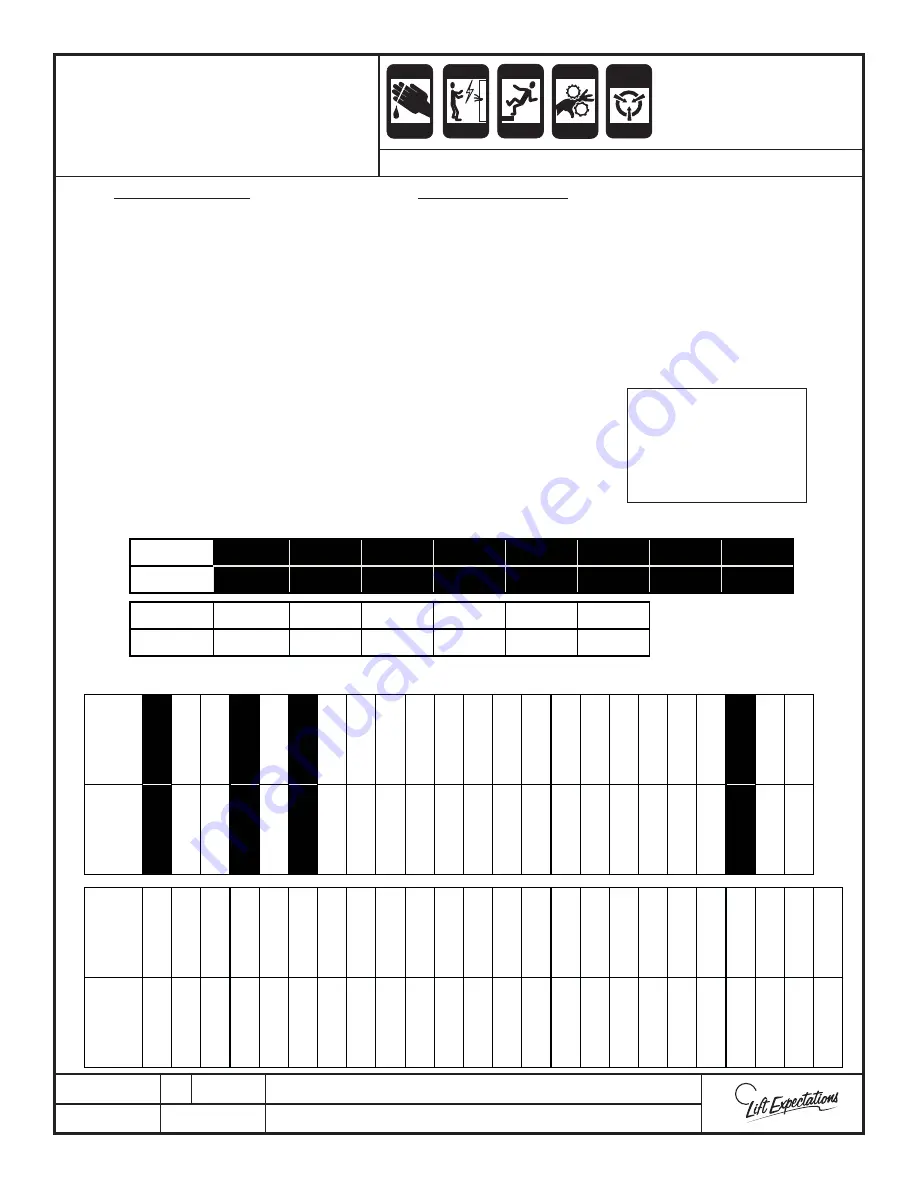
MAIN PLC FOR GMV/OLS UNITS
EXPANSION MODULE FOR GMV/OLS UNITS
Input Defi nitions
SC
= Slack Cable Switch
LPS
= Low Pressure Switch
GATE
= Gate Switch
ESTP
= Emergency Stop Switch
DC
= Door Closed Circuit
DL
= Door Locked Circuit
DZ
= Door Zone Sensor
LD
= Level Down Sensor
LU
= Level Up Sensor
TF = (
CR1) Limit Switch Relay
UP
= Up Contactor Input
OVLD
= Motor Overload
PF
= Power Failure Relay
1-6 F
= Floor Call Push Buttons
EZ 1-6
= EZ Magnet Sensors
SW1
= Autogate Programming Switch
Run
= Run Contactor Input
SP
= Safety Pan Relay
RS
= Reset Switch
Output Defi nitions
RUN
= Run Contactor Output
UP
= Up Contactor Output
HSV
= High Speed Valve Relay
DV
= Down Valve Relay
LR
= Cab Light Automatic Timer Relay
SV
= Up Low Speed Valve Relay
EMI 1-6
= EMI Outputs
1-6 A
= Floor Acknowledgement Lights in
the COP
AG1
= Autogate 1
AG2
= Autogate 2
AG3
= Autogate 3
DF
= Door Fault
Input (I)
0.0
0.1
0.2
0.3
0.4
0.5
0.6
0.7
Indica
Ɵ
on
Gate Estop
DC
DL
LPS
PS
TF
OVLD
Output (Q)
0.0
0.1
0.2
0.3
0.4
0.5
Indica
Ɵ
on
Run/In Use
Up
HSV
Down
SV
LR
Input (I)
8.0
8.1
8.2
8.3
8.4
8.5
8.6
8.7
9.0
9.1
9.2
9.3
9.4
9.5
9.6
9.7
10.0
10.1
10.2
10.3
10.4
10.5
10.6
Indica
tion
SC
UP
RUN
PF
DZ
LU
LD
EZ1
EZ2
EZ3
EZ4
EZ5
EZ6
1F
2F
3F
4F
5F
6F
SP
RS
SW1
Outputs
(Q)
8.0
8.1
8.2
8.3
8.4
8.5
8.6
8.7
9.0
9.1
9.2
9.3
9.4
9.5
9.6
9.7
10.0
10.1
10.2
10.3
10.4
10.5
10.6
10.7
Indica
tion
EMI1
EMI2
EMI3
EMI4
EMI5
EMI6
DF
1A
2A
3A
4A
5A
6A
AG
1
AG
2
AG
3
GMV/OLS
MICROPROCESSOR
INPUTS & OUTPUTS
SERIES :
114 ,116
Note: Highlighted
Inputs MUST be ON
when the elevator
is
stationary
and in
automatic mode!
Page 55


